Introduction
It is well known that there are numerous factors
that influence the stability of an implant, such as the amount of
bone surrounding the implant and the quality of that bone (1), the size (2) and type (3) of implant and whether it is associated
with one or two bony cortices (4).
Implant length has proved to be an important factor for the success
of implantation, particularly for the atrophied posterior maxilla
area (5,6); however, to the best of our knowledge,
none of these studies have evaluated the association between
implant apex and sinus floor cortical bone. Jeong et al
(7) reported that bicortical
implantation had the potential to increase the initial stability
and reduce the stress of the cortical bone around the implant
neck.
A key factor for the success or failure of a dental
implant is the manner in which stresses are transferred to the
surrounding bone (8), particularly
for immediate loading implantation. It is not difficult to imagine
that the sinus floor cortical bone can provide a support force for
the implant. As the implant apex gets closer to the sinus floor,
the cortical bone will stop the stress distribution and provide a
bigger supporting force for the implant; however this conjecture is
not easily verified by clinical studies.
Finite element analysis (FEA) has been widely used
to predict the effect of clinical factors on the success of
implantation, and also to estimate the biomechanical performance
associated with various alveolar bone and dental implant conditions
(9). FEA allows the prediction of
the stress distribution in the contact area of the implants with
cortical bone, and around the apex of the implants in the
surrounding bone. This method is advantageous for solving complex
structural problems as it divides them into smaller and simpler
inter-related sections through the use of mathematical techniques
(10). Resonance frequency
analysis (RFA) is a nondestructive measurement that has been
extensively used in clinical practice over the last five years
(11). Resonance frequency, as a
type of physical property, can also be simulated by FEA and has
already been used in the biomechanical research of dental
implantation (12,13).
In the present study, three-dimensional (3D) FE
models and an implant were constructed. All factors other than the
distance between the implant apex and the sinus floor cortical bone
were excluded, in order to observe the association between
them.
Materials and methods
Implant system
The standard implant with a diameter of 4.0 mm and a
length of 10.0 mm was modeled and placed in the 3D FE models of the
sinus area. The shape and structure of the implant was modeled
according to the Nobel Biocare® implant system (Nobel
Biocare, Kloten, Switzerland). In order to simplify the analysis,
the implant and the abutment were modeled as a unit.
Sinus geometric modeling
3D-CAD models of the posterior maxilla with 0.3-mm
thick (14) sinus membranes,
different heights of alveolar ridge and different thicknesses of
sinus floor cortical bone were generated using CAD software
(SolidWorks 2012, Fukuoka, Japan). The geometry of the maxilla was
defined by a bucco-palatal section according to the anatomical
aspects of the sinus area (15–18).
Six models (models 1-1 to 1-6) were used to research different
distances between the implant apex and sinus floor cortical bone.
The alveolar ridge heights of these models were between 10 and 14
mm, with 1 mm crestal cortical bone and sinus floor cortical bone.
For model 1-1, the implant apex just broke through the sinus floor
cortical bone (the upper surface of the sinus floor cortical bone
and the apical surface of the implant were at the same level); for
model 1-2, the implant apex broke through half the thickness of the
sinus floor cortical bone; for model 1-3, the implant apex just
made contact with the lower surface of the sinus floor cortical
bone; and for the remaining models the implant apexes gradually
deviated from the sinus floor. The other four models (models 2-1 to
2-4), with the same alveolar ridge height of 11 mm, were generated
to investigate the different depths that the implant was embedded
in different thicknesses of sinus floor cortical bone. The
thickness of the sinus floor cortical bone changed from 0.5 mm to
2.0 mm in increments of 0.5 mm; relative to the sinus floor
cortical bone the implant apex was thus separate, in contact with,
penetrating through one-quarter of the bone thickness or
penetrating through one-half of the bone thickness, respectively.
According to the design of the study, models 2-2 and 1-3 were the
same: Alveolar ridge height, 11 mm; crestal cortical bone
thickness, 1 mm; and sinus floor cortical bone thickness, 1 mm.
Material properties
The material properties of different types of
tissue, as well as the titanium implants in the models, were
assumed to be homogeneous, isotropic and linearly elastic. Young’s
modulus, Poisson’s ratio and the mass density of the materials used
in the analysis were taken from the literature (2,19,20)
and are shown in Table I.
 | Table IProperties ascribed to materials used
in the finite element models. |
Table I
Properties ascribed to materials used
in the finite element models.
| Material | Young’s modulus
(MPa) | Poisson’s ratio | Mass density
(g/cm3) |
|---|
| Titanium
implanta | 103,400 | 0.35 | 4.5 |
| Cortical bonea | 13,700 | 0.30 | 2.0 |
| Cancellous bone
(D3)a | 1,370 | 0.30 | 1.0 |
| Sinus
membraneb | 58 | 0.45 | 1.0 |
Interface conditions
The models were prepared with two types of interface
conditions: One represented ideal osseointegration for traditional
loading (loaded onto the body without force), with 100% union
between the implants and maxilla; for the other type, the
implant-bone interface was assumed to be a frictional interface
(prior to osseous integration, i.e. immediate loading). In total,
there were thus four groups: Groups 1 and 2 were based on models
1-1 to 1-6 with interface conditions of either immediate or
conventional loading, respectively; groups 3 and 4 were based on
models 2-1 to 2-4, also with interface conditions of either
immediate or conventional loading, respectively. To ensure initial
stability for the immediate loading condition, the model was
constructed using nonlinear frictional contact elements, which
allowed minor displacements between the implant and bone. Under
these conditions, the contact zone transfers pressure and
tangential forces (i.e. friction) but no tension. The friction
coefficient between the implant and bone was set to 0.3 (21).
Loading and boundary conditions
An average force of 129 N (22) inclined 30° posteriorly relative to
the implant axis and 30° away from the sagittal plane was dispersed
on the top of the implant abutment. ANSYS 12.1 FE software (ANSYS
Inc., Harbin, China) was used for the FEA. The models were
constrained in all directions at the nodes on the medial and distal
bone surfaces, the top of the simulated sinus, the sinus walls and
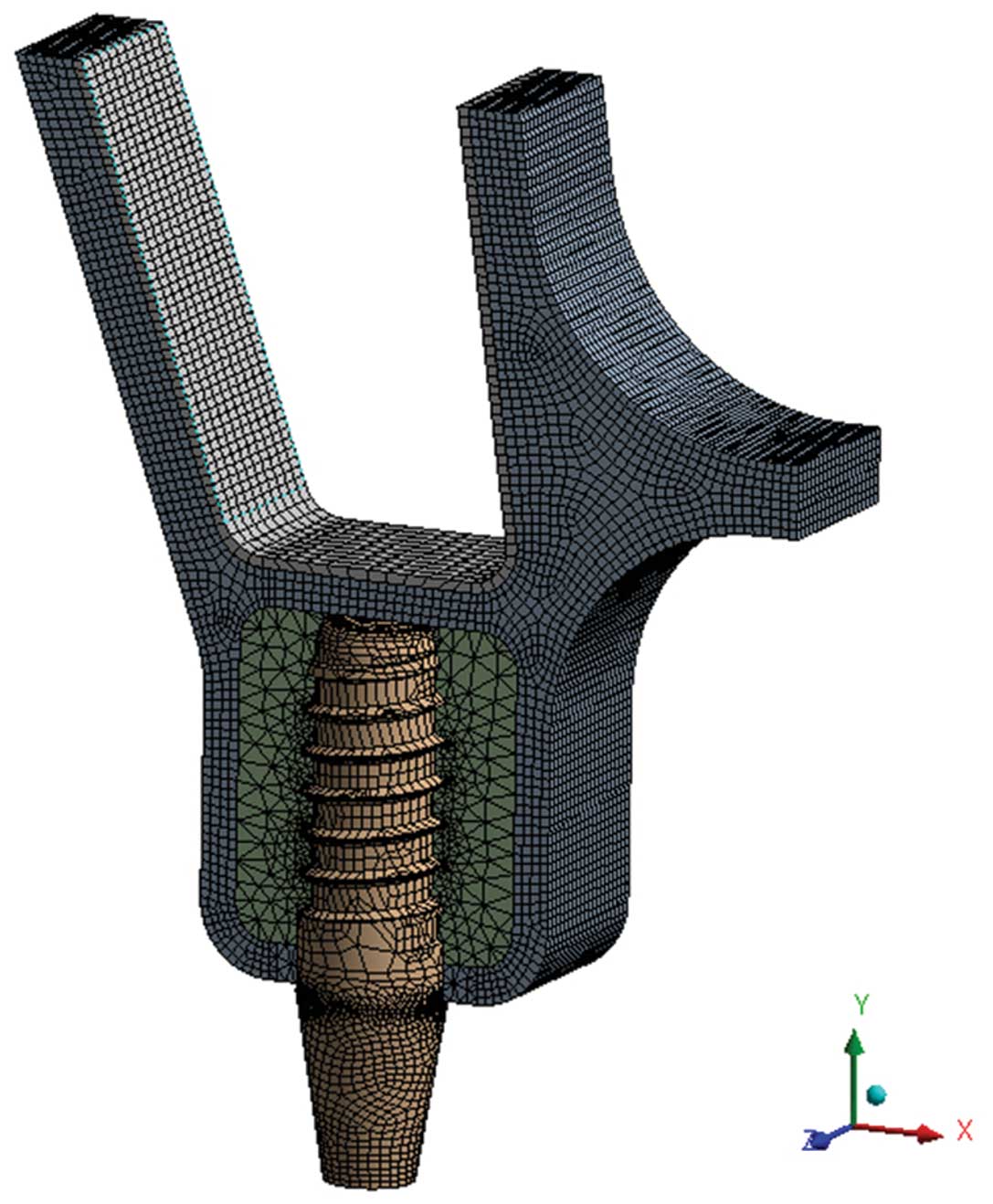
the sinus membrane. The models were meshed with four-node
tetrahedral elements and eight-node hexahedral elements and
composed of total elements varying from 94,453 to 106,347 and total
nodes ranging from 333,087 to 369,874 (Fig. 1). To assess the distribution of
stresses, maximum von Mises stresses were visualized with stress
contour plots. The biomechanical effects were also analyzed by
considering the maximum displacement of the implant neck and apex.
Additionally, buccolingual and axial resonance frequencies of the
implant were analyzed.
Statistical analysis
Data were evaluated by t-tests, and P≤0.05 was
considered to indicate a statistically significant difference.
Results
Stress distribution and maximum von Mises
stress
Cortical bones of the alveolar ridge
and sinus floor
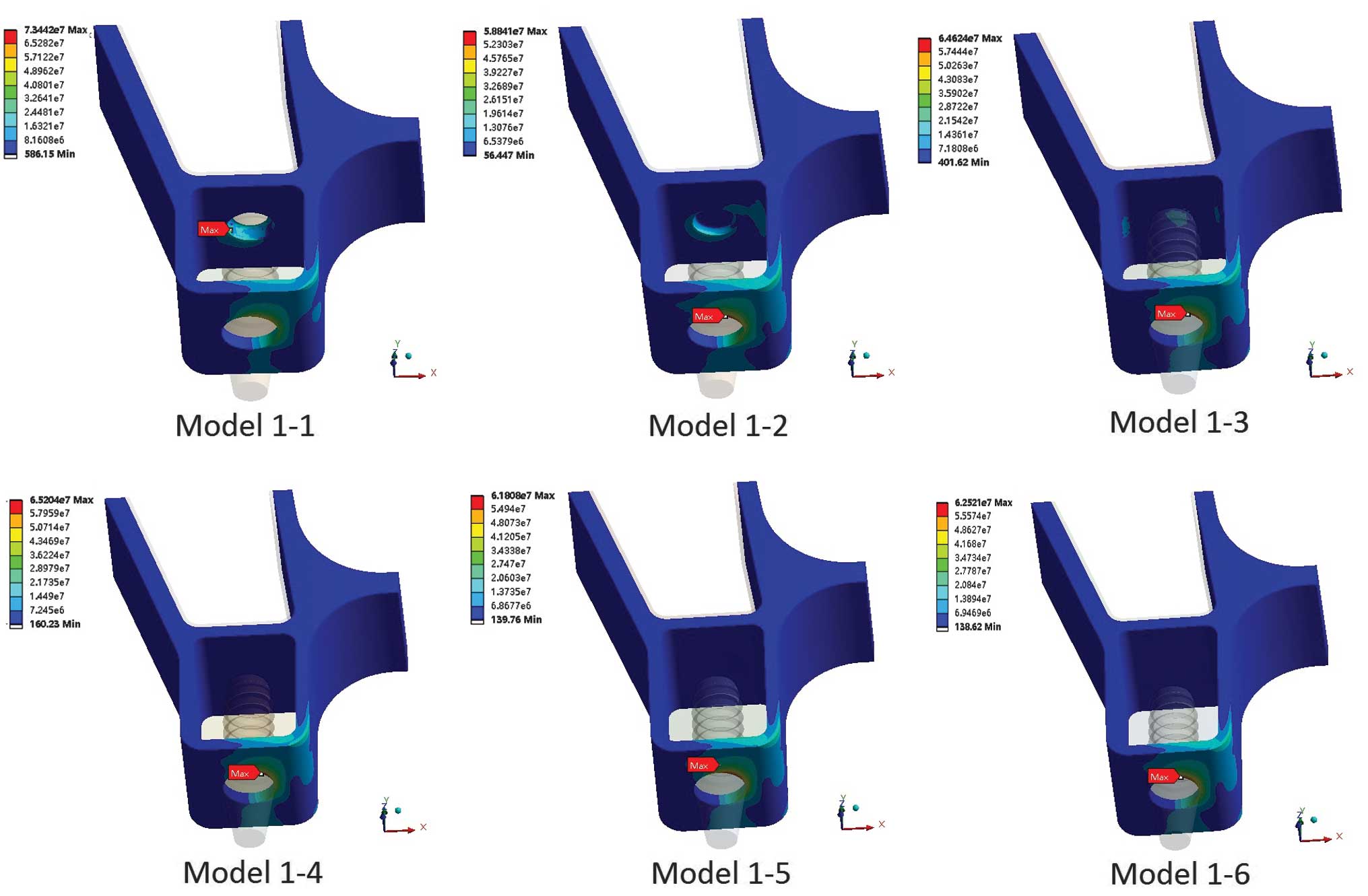
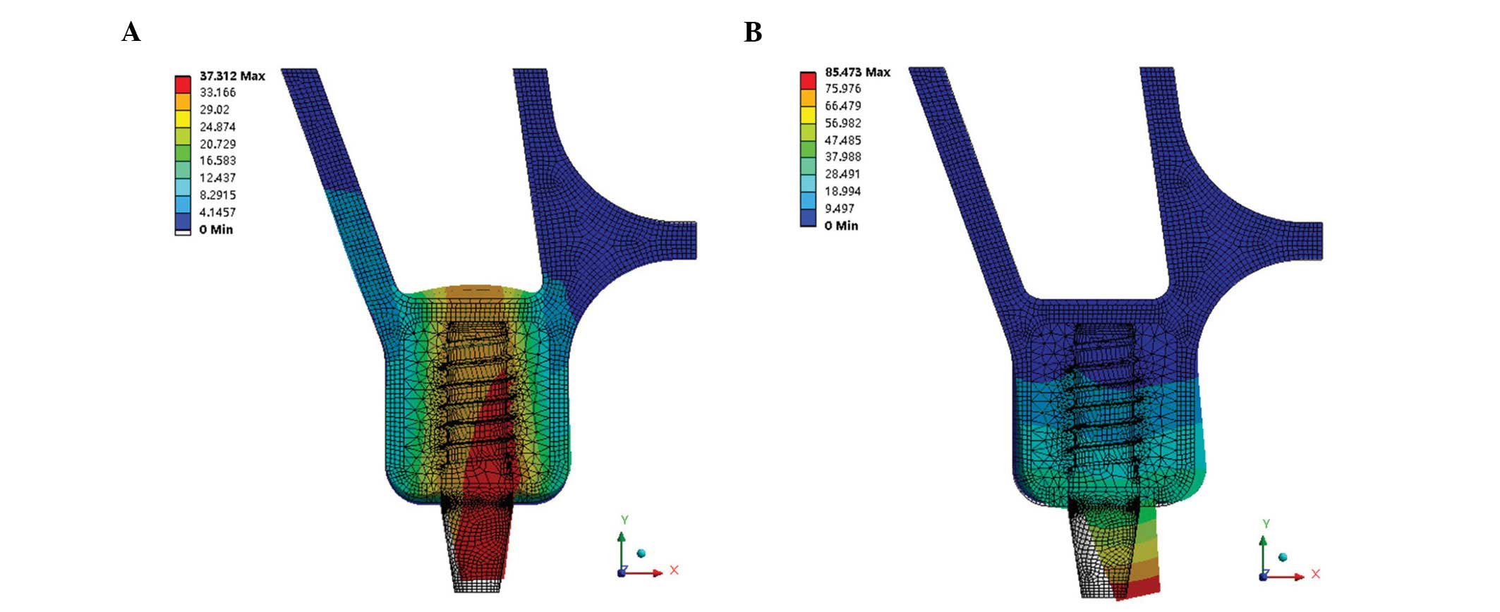
The stress distributions of the cortical bone in
immediate loading are shown in Fig.
2 (groups 1 and 2) and Fig. 3
(groups 3 and 4). Maximum von Mises stresses were also analyzed and
are shown in Fig. 4A (groups 1 and
2) and Fig. 4B (groups 3 and
4).
The von Mises stress was concentrated on the surface
of the crestal cortical bone around the implant neck, with the
exception of that in model 1-1 (immediate loading) (Figs. 2 and 3). In model 1-1 (bicortical
implantation), the implant apex broke through the sinus floor
cortical bone, which resulted in the sinus floor cortical bone
suffering more stress (73.44 MPa) than the crestal cortical bone
(58.69 MPa) (Fig. 4A). The results
of Fig. 4A show that the maximum
von Mises stress of immediate loading was ~18% lower than that of
conventional loading. The maximum von Mises stress of the crestal
cortical bone increased with the increasing distance between the
implant apex and the upper surface of the sinus floor cortical
bone. Until the implant apex separated from the lower surface of
the sinus floor cortical bone (model 1-4), the stress reached a
peak value and then decreased with increasing distance, whether the
loading was immediate or conventional. The stress of the sinus
floor cortical bone was higher with immediate loading than that
with conventional loading prior to the implant apex and sinus floor
cortical bone separating. When there was cancellous bone between
the implant apex and the sinus floor cortical bone, the stress of
the sinus floor cortical bone was approximately the same in
immediate and conventional loading.
The results of Fig.
4B show that the different penetration distances of the implant
apex into the sinus floor cortical bone had little effect on the
maximum von Mises stress of the crestal cortical bone (P>0.05);
however the stress of the sinus floor cortical bone with immediate
loading was affected, and the maximum von Mises stress increased
from 6.01 to 34.48 MPa.
Sinus membrane
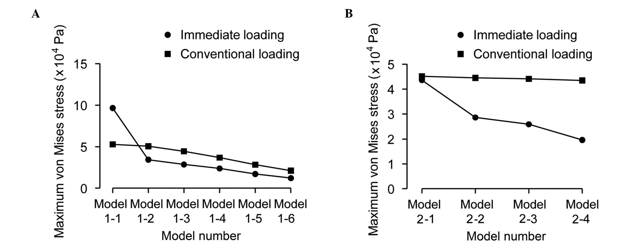
Maximum von Mises stresses of the sinus membrane
were analyzed and are shown in Fig.
5A (groups 1 and 2) and Fig.
5B (groups 3 and 4). Fig. 5A
shows that, as the distance increased between the implant apex and
the upper surface of the sinus floor cortical bone, the maximum von
Mises stress decreased significantly, particularly between models
1-1 and 1-2, with immediate loading. Fig. 5B shows that changing the distance
that the implant apex pierced into the sinus floor cortical bone
had little effect in reducing the maximum von Mises stress of the
sinus membrane in conventional loading (P>0.05) but showed a
marked effect in immediate loading; in immediate loading, the
maximum von Mises stress decreased from 4.36×10⁴ to
1.96×10⁴ Pa.
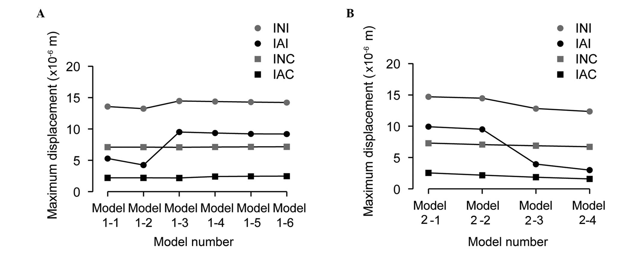
Implant displacement
The data of the maximum displacements of the implant
neck and apex are shown in Fig. 6A
(groups 1 and 2) and Fig. 6B
(groups 3 and 4). The implant displacement cloud chart of group 3
is shown in Fig. 7 as an example.
The results showed that the maximum displacement of the implant
neck was bigger than that of the implant apex in all the models.
For immediate loading, when the implant apex broke through or
inside the sinus floor cortical bone, the implant maximum
displacements, particularly for the implant apex, were smaller than
those for the other conditions (Fig.
6A). As the depth the implant apex reached into the sinus floor
cortical bone increased, the maximum displacements decreased
(Fig. 6B). For conventional
loading, as the distance between the implant apex and the sinus
floor cortical bone increased, the maximum displacements of the
implant neck and apex increased, although inconspicuously. As the
depth the implant apex reached into the sinus floor cortical bone
increased, the maximum displacements of the implant apex decreased
significantly.
Implant resonance frequencies
Fig. 8 shows the
two vibrational modes of the implant-bone system. The data of
implant axial resonance frequencies are shown in Fig. 9A (groups 1 and 2) and Fig. 9B (groups 3 and 4), and implant
buccolingual resonance frequencies are shown in Fig. 10A (groups 1 and 2) and Fig. 10B (groups 3 and 4). As the
distance between the implant apex and the sinus floor cortical bone
lengthened (Fig. 9A), the values
of the axial resonance frequencies increased significantly between
models 1-1 and 1-2 in immediate and conventional loading. The
resonance frequencies subsequently increased slowly. As the depth
the implant apex penetrated into the sinus floor cortical bone
increased, the axial resonance frequencies exhibited a linear
upward tendency (Fig. 9B). The
buccolingual resonance frequencies imperceptibly decreased as the
distance between the implant apex and sinus floor cortical bone
lengthened. No significant changes in frequency were observed when
the penetration depth into the sinus floor cortical bone was
adjusted (Fig. 10).
Discussion
Mechanical analysis using the FE method has
previously been utilized to reliably and accurately reveal the
biomechanical behavior around dental implants without the risk or
expense of implantation (2). The
sinus area of the posterior maxilla is complex and it is not easy
to establish an accurate and valid 3D FE model. In FEM research of
a maxilla sinus area implant, Okumura et al (24) found no marked difference between
conventional simplified 3D FE models and the full maxilla model
created from computed tomography (CT) Digital Imaging and
Communications in Medicine data. In order to exclude the influence
of the anatomical variations of bone and to improve the
comparability of the models, as suggested by Akca and Cehreli
(25), the models used in the
present study required a change in the height of the alveolar bone
and the thickness of the sinus floor cortical bone. It was decided
not to use an anatomical model of the maxilla provided by cone beam
CT data; instead, 3D CAD models based on the anatomical data of the
sinus area have been developed in this study.
Due to the poor quality and size of the alveolar
ridge, the success rate of sinus area implantation is relatively
low. Numerous studies have been conducted into dental implantation
in the posterior maxilla (26,27),
and clinical studies, animal experiments and FEM studies (28–30)
have been carried out regarding the influence of bone quality and
size on implants; however, to the best of our knowledge, no study
concerning the association between an implant and the sinus floor
cortical bone has been conducted. Sinus floor cortical bone has a
tendency to be thin, which has made it less important in the
research of dental implantation in the sinus area.
The results of the present study showed that the
association between the implant apex and the sinus floor cortical
bone affected the stress distribution of the cortical bone, the
implant micromotion and the implant resonance frequencies. In the
clinic, it is usual to select an implant that is a little shorter
than the height of the alveolar ridge to keep the implantation
safe. The study showed that if the height of the alveolar ridge is
much longer than the implant length, it may not benefit the
stability of the implant. This was particularly true when the
implant apex made contact with or broke into or through the sinus
floor cortical bone, when the maximum von Mises stress of the
crestal cortical bone around the implant neck was reduced and
whether loading was immediate or conventional. When the implant
apex just broke through the sinus floor cortical bone in immediate
loading (bicortical implantation), the sinus floor cortical bone
suffered more stress than the implant neck cortical bone, which may
increase the success rate of implantation. Although, the maximum
von Mises stress of the sinus membrane was significantly increased
in bicortical implantations, the sinus membrane was not supposed to
be aggravated. Clinical and animal studies have shown that sinus
membrane contact with the implant apex in sinus floor elevation
without bone grafts also has a good success rate, without
inflammation of aggravation of the sinus membrane (30,31).
With regard to implant micromotion in the condition
of immediate loading, when the implant apex made contact with the
lower surface of the sinus floor cortical bone or broke into the
sinus floor cortical bone, implant displacements of the neck and
apex decreased significantly. This result indicated that the sinus
floor cortical bone was beneficial to the initial stability of the
implant. In particular, when the implant apex was inside the sinus
floor cortical bone, implant micromotion was reduced, and not too
much stress passed to the sinus membrane; thus, a situation where
the sinus floor cortical bone is thick enough to insert the implant
apex inside it but without breaking through may be a better design
of surgical treatment. For conventional loading, due to good
osseointegration, the bone around the implant apex may not greatly
affect the implant stability.
RFA as a nondestructive measurement has been widely
used in clinical practice in the last five years (11) but only buccolingual resonance
frequencies are checked. There are, in fact, numerous types and
directions of resonance frequencies that cannot be examined,
particularly the axial resonance frequency. In an FEA study, both
buccolingual and axial resonance frequencies can be tested. The
present results showed that, as the implant apex moved closer to
the sinus floor cortical bone and within it, the implant axial
resonance frequency increased but a change in the buccolingual
resonance frequency was not evident. This suggests that the sinus
floor cortical bone was beneficial in reducing implant axial
resonance frequency, particularly when the implant apex was inside
the sinus floor cortical bone. This means that the sinus floor
cortical bone can improve implant stability in the axial direction
but not the buccolingual direction.
In conclusion, this FE study of the association
between the implant apex and the sinus floor cortical bone showed
that the sinus floor cortical bone is beneficial for implant
stability, particularly for immediate loading. In the situation
where the implant apex contacts with, breaks into or breaks through
the sinus floor cortical bone a significant reduction in the
maximum von Mises stress of the sinus floor cortical bone, implant
displacement and axial resonance frequencies can be observed.
Further research concerning bicortical dental implantation in the
posterior maxilla is required.
Acknowledgements
This study was supported by the National High
Technology Research and Development Program of China (Program 863,
2011AA030107) and the Young Scholars Foundation (School of
Stomatology, China Medical University, Shenyang, China) (grant
K101593-12-34). The authors would like to thank the Regenerative
Dentistry and Implant Center, and the Section of Removable
Prosthodontics (Division of Oral Rehabilitation, Faculty of Dental
Science, Kyushu University, Fukuoka, Japan) for their support and
permission to use their facilities.
References
|
1
|
Winter W, Krafft T, Steinmann P and Karl
M: Quality of alveolar bone - structure-dependent material
properties and design of a novel measurement technique. J Mech
Behav Biomed Mater. 4:541–548. 2011. View Article : Google Scholar : PubMed/NCBI
|
|
2
|
Ding X, Zhu XH, Liao SH, Zhang XH and Chen
H: Implant-bone interface stress distribution in immediately loaded
implants of different diameters: a three-dimensional finite element
analysis. J Prosthodont. 18:393–402. 2009. View Article : Google Scholar : PubMed/NCBI
|
|
3
|
Meredith N, Books K, Friberg B, Jemt T and
Sennerby L: Resonance frequency measurements of implant stability
in vivo. A cross-sectional and longitudinal study of resonance
frequency measurements on implants in the edentulous and partially
dentate maxilla. Clin Oral Implants Res. 8:226–233. 1997.
View Article : Google Scholar : PubMed/NCBI
|
|
4
|
Mohammed Ibrahim M, Thulasingam C, Nasser
KS, Balaji V, Rajakumar M and Rupkumar P: Evaluation of design
parameters of dental implant shape, diameter and length on stress
distribution: a finite element analysis. J Indian Prosthodont Soc.
11:165–171. 2011. View Article : Google Scholar :
|
|
5
|
Lee JH, Frias V, Lee KW and Wright RF:
Effect of implant size and shape on implant success rates: a
literature review. J Prosthet Dent. 94:377–381. 2005. View Article : Google Scholar : PubMed/NCBI
|
|
6
|
Toniollo MB, Macedo AP, Rodrigues RC,
Ribeiro RF and de Mattos Mda G: Three-dimensional finite element
analysis of stress distribution on different bony ridges with
different lengths of morse taper implants and prosthesis
dimensions. J Craniofac Surg. 23:1888–1892. 2012. View Article : Google Scholar : PubMed/NCBI
|
|
7
|
Jeong CM, Caputo AA, Wylie RS, Son SC and
Jeon YC: Bicortically stabilized implant load transfer. Int J Oral
Maxillofac Implants. 18:59–65. 2003.PubMed/NCBI
|
|
8
|
Geng JP, Tan KB and Liu GR: Application of
finite element analysis in implant dentistry: a review of the
literature. J Prosthet Dent. 85:585–598. 2001. View Article : Google Scholar : PubMed/NCBI
|
|
9
|
Van Staden RC, Guan H and Loo YC:
Application of the finite element method in dental implant
research. Comput Methods Biomech Biomed Engin. 9:257–270. 2006.
View Article : Google Scholar : PubMed/NCBI
|
|
10
|
Bozkaya D, Muftu S and Muftu A: Evaluation
of load transfer characteristics of five different implants in
compact bone at different load levels by finite elements analysis.
J Prosthet Dent. 92:523–530. 2004. View Article : Google Scholar : PubMed/NCBI
|
|
11
|
Chang PC, Lang NP and Giannobile WV:
Evaluation of functional dynamics during osseointegration and
regeneration associated with oral implants. Clin Oral Implants Res.
21:1–12. 2010. View Article : Google Scholar : PubMed/NCBI
|
|
12
|
Huang HM, Lee SY, Yeh CY and Lin CT:
Resonance frequency assessment of dental implant stability with
various bone qualities: a numerical approach. Clin Oral Implants
Res. 13:65–74. 2002. View Article : Google Scholar : PubMed/NCBI
|
|
13
|
Pattijn V, Van Lierde C, Van der Perre G,
Naert I and Vander Sloten J: The resonance frequencies and mode
shapes of dental implants: Rigid body behaviour versus bending
behaviour. A numerical approach. J Biomech. 39:939–947. 2006.
View Article : Google Scholar : PubMed/NCBI
|
|
14
|
Pommer B, Unger E, Sütö D, Hack N and
Watzek G: Mechanical properties of the Schneiderian membrane in
vitro. Clin Oral Implants Res. 20:633–637. 2009.PubMed/NCBI
|
|
15
|
Underwood AS: An inquiry into the anatomy
and pathology of the maxillary sinus. J Anat Physiol. 44:354–369.
1910.PubMed/NCBI
|
|
16
|
Ulm CW, Solar P, Gsellmann B, Matejka M
and Watzek G: The edentulous maxillary alveolar process in the
region of the maxillary sinus - a study of physical dimension. Int
J Oral Maxillofac Surg. 24:279–282. 1995. View Article : Google Scholar : PubMed/NCBI
|
|
17
|
van den Bergh JP, ten Bruggenkate CM,
Disch FJ and Tuinzing DB: Anatomical aspects of sinus floor
elevations. Clin Oral Implants Res. 11:256–265. 2000. View Article : Google Scholar
|
|
18
|
Gosau M, Rink D, Driemel O and Draenert
FG: Maxillary sinus anatomy: a cadaveric study with clinical
implications. Anat Rec (Hoboken). 292:352–354. 2009. View Article : Google Scholar
|
|
19
|
Rues S, Lenz J, Schierle HP, Schindler HJ
and Schweizerhof K: Simulation of the sinus floor elevation. Proc
Appl Math Mech. 4:368–369. 2004. View Article : Google Scholar
|
|
20
|
Huang CC, Chen LW, Wu DF and Chen YC:
Finite element simulations of the contact stress between rotary
sinus lift kit and sinus membrane during lifting process. Life Sci
J. 9:167–171. 2012.
|
|
21
|
Mellal A, Wiskott HW, Botsis J, Scherrer
SS and Belser UC: Stimulating effect of implant loading on
surrounding bone. Comparison of three numerical models and
validation by in vivo data. Clin Oral Implants Res. 15:239–248.
2004. View Article : Google Scholar : PubMed/NCBI
|
|
22
|
Morneburg TR and Pröschel PA: Measurement
of masticatory forces and implant loads: a methodologic clinical
study. Int J Prosthodont. 15:20–27. 2002.PubMed/NCBI
|
|
23
|
Lekholm U, Zarb GA and Albrektsson T:
Tissue Integrated Prostheses: Osseointegration in Clinical
Dentistry. Quintessence Publishing; Chicago, IL, USA: pp. 199–209.
1985
|
|
24
|
Okumura N, Stegaroiu R, Nishiyama H,
Kurokawa K, Kitamura E, Hayashi T and Nomura S: Finite element
analysis of implant-embedded maxilla model from CT data: comparison
with the conventional model. J Prosthodont Res. 55:24–31. 2011.
View Article : Google Scholar
|
|
25
|
Akca K and Cehreli MC: Biomechanical
consequences of progressive marginal bone loss around oral
implants: a finite element stress analysis. Med Biol Eng Comput.
44:527–535. 2006. View Article : Google Scholar : PubMed/NCBI
|
|
26
|
Cannizzaro G, Felice P, et al: Early
implant loading in the atrophic posterior maxilla: 1-stage lateral
versus crestal sinus lift and 8 mm hydroxyapatite-coated implants.
A 5-year randomised controlled trial. Eur J Oral Implant. 6:13–25.
2013.
|
|
27
|
Doan N, Du Z, Crawford R, Reher P and Xiao
Y: Is flapless implant surgery a viable option in posterior
maxilla? A review. Int J Oral Maxillofac Surg. 41:1064–1071. 2012.
View Article : Google Scholar : PubMed/NCBI
|
|
28
|
Wang D, Künzel A, Golubovic V, et al:
Accuracy of peri-implant bone thickness and validity of assessing
bone augmentation material using cone beam computed tomography.
Clin Oral Investig. 17:1601–1609. 2013. View Article : Google Scholar
|
|
29
|
Chou IC, Lee SY, Wu MC, Sun CW and Jiang
CP: Finite element modelling of implant designs and cortical bone
thickness on stress distribution in maxillary type IV bone. Comput
Methods Biomech Biomed Engin. 17:516–526. 2014. View Article : Google Scholar
|
|
30
|
Sul SH, Choi BH, Li J, Jeong SM and Xuan
F: Histologic changes in the maxillary sinus membrane after sinus
membrane elevation and the simultaneous insertion of dental
implants without the use of grafting materials. Oral Surg Oral Med
Oral Pathol Oral Radiol Endod. 105:e1–e5. 2008. View Article : Google Scholar : PubMed/NCBI
|
|
31
|
Pjetursson BE, Rast C, Brägger U,
Schmidlin K, Zwahlen M and Lang NP: Maxillary sinus floor elevation
using the (transalveolar) osteotome technique with or without
grafting material. Part I: Implant survival and patients’
perception. Clin Oral Implants Res. 20:667–676. 2009. View Article : Google Scholar : PubMed/NCBI
|


