Introduction
Knee osteoarthritis (OA) is prevalent among
middle-aged and older adults. The primary pathology involves the
degeneration and destruction of the articular cartilage structure.
Unicompartmental disease constitutes ~1/3 of knee OA cases, with
most cases being medial compartment OA (1). This facilitated the development of
unicondylar knee arthroplasty (UKA). Unlike total knee
arthroplasty, UKA replaces only the surface of the affected side
compartment, retaining the healthy side compartment and the
inherent soft tissue of the knee joint (2). This procedure has the advantages of
minimal trauma and a rapid recovery. However, it is important to
consider the postoperative complications of UKA, including the
premature wear of polyethylene, aseptic loosening of the
prosthesis, osteolysis and periprosthetic fractures (3). Aseptic loosening and osteolysis are
directly related to the wear of polyethylene liners (4).
UKA prostheses are classified into fixed and movable
pads based on their type of activity. The UKA movable liner is a
polyethylene liner with obvious slippage relative to the tibial
component. Its mobility is high, and the impact between the bone
and the implant and between the implants will affect wear (5). The UKA fixed liner is a polyethylene
liner that has no slip relative to the tibial component. Stress
concentrations at the liner contact surface increase the risks of
wear and structural fatigue failure (6). The study of unicondylar joint wear is
of great significance as it is one of the main factors limiting the
life of the prosthesis. The long-term survival rate of unicondylar
joints is affected by the angle of prosthesis placement and
accuracy of lower limb alignment reconstruction (7). An important surgical parameter in UKA
is the posterior tilt angle of the tibial prosthesis. The choice of
a suitable posterior tilt angle for UKA remains controversial for
surgeons. Excessive retroversion can lead to abnormal knee joint
kinematics, early prosthesis loosening and increased risk of
anterior cruciate ligament rupture and periprosthetic fractures,
resulting in higher postoperative revision rates (8).
Finite element analysis (FEA) is a valuable tool for
studying the biomechanical changes in knee joints after joint
prosthesis replacement. It has been widely used in various
orthopedic research fields in recent years, owing to its ability to
quantitatively analyze the mechanical properties of materials. The
data obtained from this method are intuitive and not limited by
experimental conditions (9). Weber
et al (10) developed an
UKA model on a mobile platform. They concluded that the optimal
posterior tilt angle should be determined based on the patient's
preoperative and expected postoperative kinematics, ligament status
and location of retropatellar cartilage damage. However, they only
analyzed the mobile platform and not the tilt angle of the fixed
platform. Iesaka et al (11) and Sawatari et al (12) established fixed platform UKA tibia
models. The authors noted that the posterior tilt should be
<10˚. However, the model is relatively simple.
The purpose of the present study was to establish a
fixed-platform UKA model using a FEA method. The tibial plateau
posterior inclination angles were set as 3, 6 and 9˚, and the
stress changes in the internal structures of each model were
compared after applying knee flexion movements. The present study
aimed to provide a theoretical basis for rational selection of the
posterior tilt angle of the tibial plateau during surgery.
Materials and methods
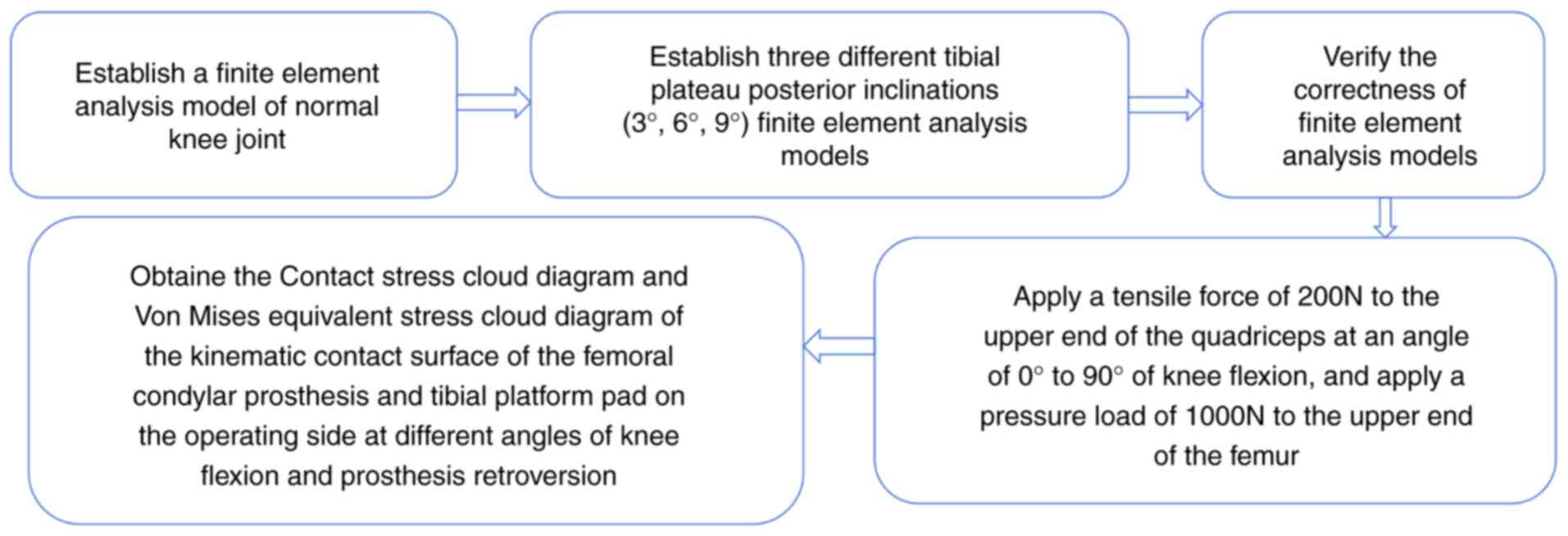
A flowchart of the FEA flow chart is revealed in
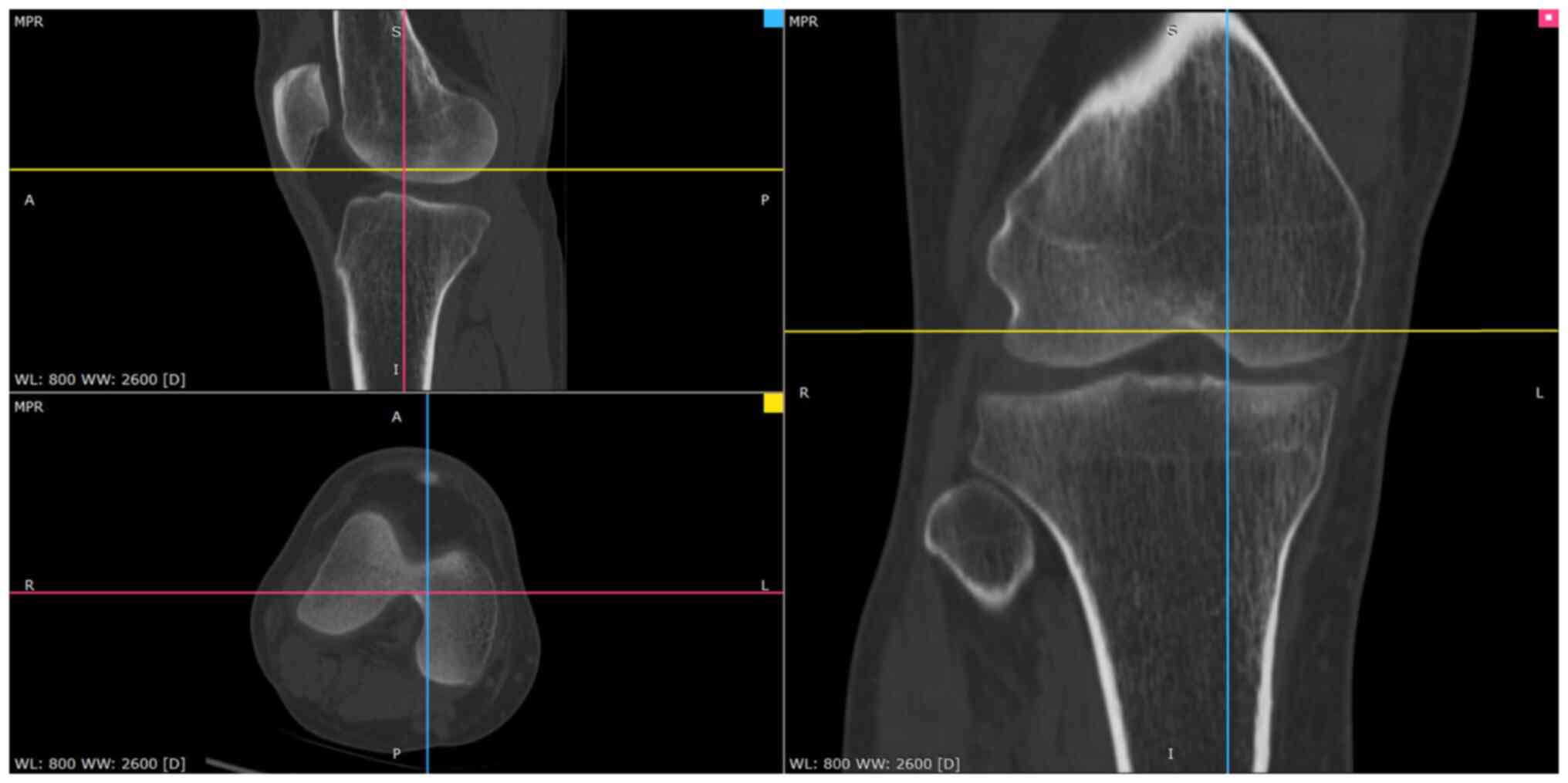
Fig. 1. First, the Digital Imaging
and Communications in Medicine file of the unilateral knee joint
computed tomography (CT) and magnetic resonance imaging (MRI) scan
data of a volunteer, 35 years-old male, 172.5 cm tall, and 69.4 kg
in weight, was selected. The research protocol was reviewed and
approved (approval no. CZEYYL2023016) by the Ethics Committee of
Changzhi Second People's Hospital (Changzhi, China). The
participant provided written informed consent before participating
in the present study and underwent image scanning in October 2023
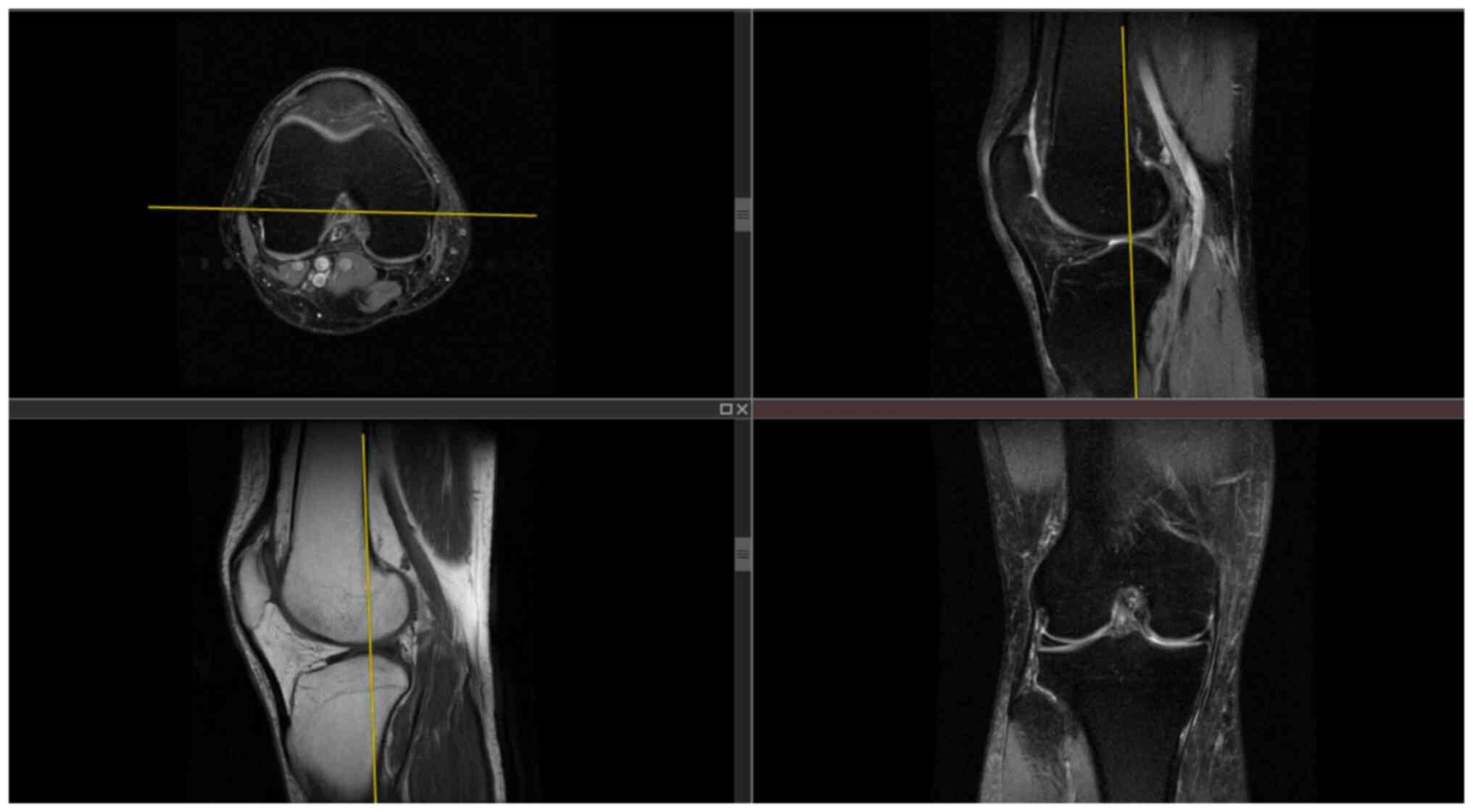
at the Second People's Hospital of Changzhi. CT images and MRI
images are revealed in Figs. 2 and
3, respectively. The
anteroposterior, lateral, double oblique and dynamic X-rays of the
knee joint were selected, while bone deformities, fractures,
tumors, infections and other diseases were excluded to obtain
normal unilateral knee joint data. Mimics 21.0 software
(Materialize, Inc.) was used to extract the data and reconstruct a
normal knee joint STL model. In the Geomagic Studio 2014 software
(Raindrop Geomagic, Inc.), the noise was repaired and reduced,
surfaced, and three different geometric solid standard for the
exchange of product (STP) models of the tibial platform pad
posterior inclination corresponding to the unicondylar fixed
platform prosthesis replacement of the knee joint were reversely
processed. According to the UKA surgical protocol, the osteophytes
on the medial femoral condyle and medial and lateral edges of the
intercondylar notch were cleared and an osteotomy was performed
precisely 2 mm below the lowest point of the tibial plateau. The
femoral component was parallel to the long axis of the tibia in the
coronal position and to the long axis of the femur in the sagittal
position. The tibial component had posterior inclination angles of
3, 6 and 9˚ with the long axis of the tibia in the sagittal
position. Taking the long axis of the tibia as an example, its
determination method involves determining the midpoint of two lines
connecting the anterior and posterior cortical bones distal to the
knee joint line on the medial tibial platform (13,14).
The LIDAKANG unicondylar fixed-platform prosthesis model was
selected for matching according to the actual size parameters of
the femur and tibia. The femoral condyle prosthesis and platform
pad were made of M# (mid-sized prosthesis). During the model
processing, the corresponding femoral and tibial bone ranges were
first removed, and the prosthesis was correctly and reasonably
installed according to the clinical surgical requirements. During
the installation process, the posterior inclination angles of the
tibial platform pad were set as 3, 6 and 9˚. Finally, a 1-mm thick
bone cement layer was placed between the femoral condylar
prosthesis and femur and between the platform support and tibia
(15).
Finite element meshing
The Hypermesh 14.0 software (Altair Engineering,
Inc.) was used to mesh the STP files of the three geometric models
with different tibial platform pad posterior inclination angles (3,
6 and 9˚), which were then exported to BDF files. Finite element
preprocessing MSC Patran 2019 software (NASA; hexagon.com/products/patran) was used to set the
finite element mesh properties, define material parameters, apply
loads and limit the boundary conditions. The MSC Nastran 2019
software, a finite element post-processing tool developed by NASA
(hexagon.com/products/product-groups/computer-aided-engineering-software/msc-nastran),
was used to analyze and view the calculation results. Each group of
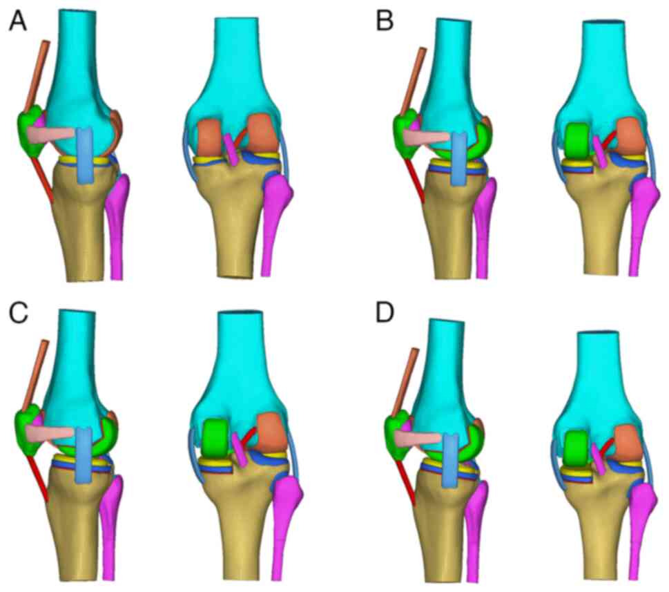
the finite-element mesh models is demonstrated in Fig. 4. Regarding the meshing of three
different tibial plateau pad posterior inclination angles (3, 6 and
9˚), the femur, tibia, fibula, patella, articular cartilage,
ligaments/tendons and unicondylar fixed platform prosthesis were
all divided using TetMesh Tet4 Element grid units, and convergence
verification was performed (16).
The number of grid units and nodes are listed in Table I.
 | Table IFinite element mesh division. |
Table I
Finite element mesh division.
| Sequence | Group | Number of nodes | Number of units |
|---|
| 1 | Normal group | 61,345 | 273,754 |
| 2 | 3˚ backward tilt
group | 85,986 | 413,601 |
| 3 | 6˚ backward tilt
group | 84,439 | 405,849 |
| 4 | 9˚ backward tilt
group | 87,072 | 420,744 |
Material parameter setting
According to the corresponding material parameters
of the ligaments and tendons in the study of Mesfar and Shirazi
(17), the material parameters of
each knee joint structure in this FEA are listed in Table II (17-20).
Bones (cortical bones, cancellous bones) are very hard compared
with ligaments and cartilage, similar to rigid bodies. Therefore,
assuming that the bone material is linear elastic (isotropic) or
non-linear (anisotropic) has little impact on the present study.
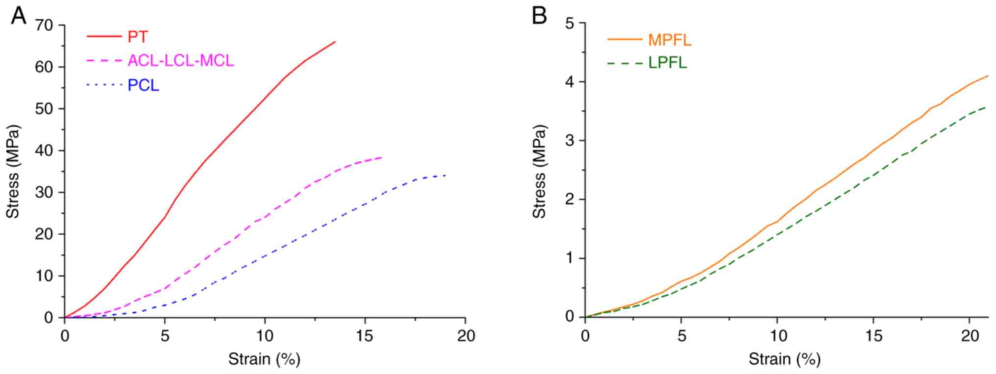
The stress-strain curves of each ligament and tendon and the
stress-strain curves of the medial and lateral retinacula are
illustrated in Fig. 5. It is
assumed that the cortical and cancellous bones, articular
cartilage, meniscus, unicondylar prosthesis and bone cement
corresponding to the femur, tibia, patella and fibula, are
isotropic, uniform and continuous linear elastic materials.
Additionally, each ligament and tendon (including the medial and
lateral patellofemoral ligaments) is considered a tension-only
non-linear material (21). The
contact friction coefficient between the meniscus and the femoral
and tibial articular cartilages was set to 0.001. The friction
coefficient between the patellar and femoral articular cartilages
was set to 0.001(22). The
cortical and cancellous bone, ligament and cortical bone, and
quadriceps tendon and cortical bone are bound and connected by
common nodes. Finally, the friction coefficient between the
unicondylar prosthesis and the liner was set to 0.07(23).
| Table IIMaterial parameters of various knee
joint structures. |
Table II
Material parameters of various knee
joint structures.
| Structure | Modulus of
elasticity (MPa) | Poisson's
ratio |
|---|
| Cortical bone | 16,200 | 0.36 |
| Cancellous
bone | 389 | 0.30 |
| Articular
cartilage | 5 | 0.46 |
| Meniscus | 59 | 0.49 |
| Quadriceps
tendon | 80 | 0.30 |
| Patellar
tendon | 116 | 0.45 |
| Ligaments
(including medial and lateral patellofemoral ligament) | 215.3 | 0.40 |
| Unicondylar femoral
prosthesis and platform support | 195,000 | 0.30 |
| Unicondylar
prosthetic liner | 685 | 0.40 |
| Bone cement
(Polymethyl Methacrylate) | 4,000 | 0.33 |
Boundary condition assumptions
The relevant published literature was referred to
set the boundary conditions, such as knee joint constraints and
loads. Grood et al (24)
pointed out that when the femur is in a constant position, the
quadriceps tendon bears an average tensile force of ~200N during
the movement of the tibia and fibula from knee flexion of 90˚ to
knee extension. In the present study, six contact pairs were set up
in the knee joint model to fix and constrain all the nodes at the
lower ends of the tibia and fibula, thereby restricting their six
degrees of freedom. The six contact pairs included the medial and
lateral femoral cartilage and the medial and lateral tibial
cartilage surface, the medial and lateral femoral cartilage surface
and the upper surface of the medial and lateral menisci, and the
tibial cartilage and lower surface of the medial and lateral
menisci. Binding constraints were set between the bone and
cartilage, the bone and ligament, the meniscus and the tibial
cartilage. In the present study, a tensile force of 200N was
applied to the upper end of the quadriceps at an angle of 0-90˚ of
knee flexion, and a pressure load of 1000N was applied to the upper
end of the femur (23) to simulate
the state of human weight-bearing knee flexion. All nodes at the
lower ends of the tibia and fibula were fixed, limiting their 6
degrees of freedom in six directions, and the femur was pushed to
complete flexion activities at different angles through rigid bone
blocks on the femoral shaft. The stress distributions in the
unicondylar prosthesis and articular cartilage at various knee
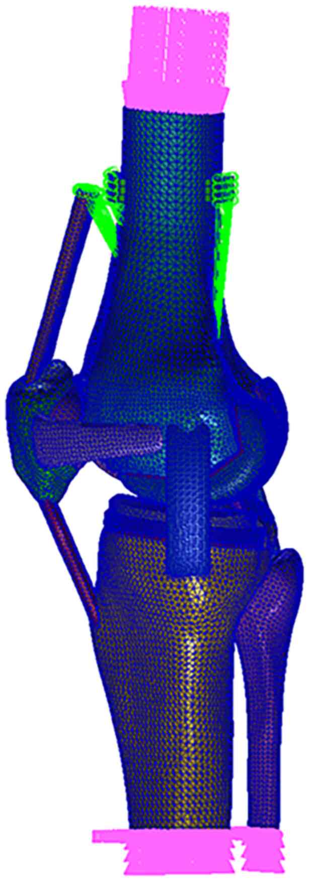
flexion angles were obtained, compared and analyzed. The finite
element boundary constraint conditions (taking the
posterior-inclined 6˚ prosthetic group as an example; the others
were similar) are demonstrated in Fig.
6.
Model verification
Axial compression and anterior tibial drawer
experiments were conducted to verify the accuracy of the normal
knee joint model. Referring to the axial experiment of Bao et
al (25), the distal ends of
the tibia and fibula were fixed, the proximal end of the femur was
loaded with 1000N axial pressure, and the compressive stress and
contact area of the tibial cartilage surface were calculated. In
addition, the proximal femur was fixed, the tibia and fibula were
coupled, and a forward force of 134N (26) was applied at the midpoint of the
medial and lateral condyles of the tibial platform to simulate the
anterior drawer test and calculate the displacement and rotation
angle of the tibia.
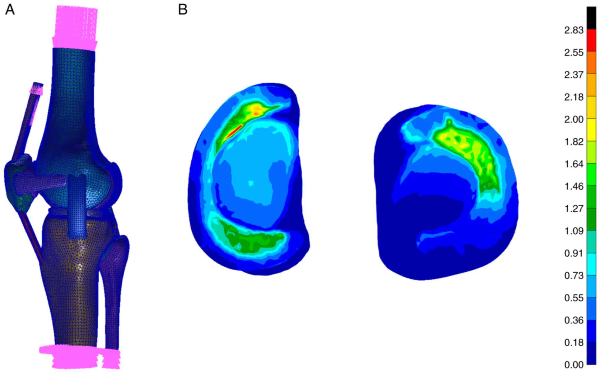
It is calculated that under the axial compression
test, the inner and outer compartments bear 55.8 and 44.2% of the
total load respectively. The peak compressive stresses on the
medial and lateral sides of the tibial plateau cartilage are 2.83
and 2.15 MPa respectively, and the medial and lateral contact areas
are 592.3 and 485.7 mm2 respectively. The contact area
between the meniscus and tibia accounts for 60.2% of the total
contact area, which is similar to the literature results (25). Under the anterior drawer
experiment, the tibia and fibula simultaneously moved forward by
5.04 mm and internally rotated by 1.92˚, which is similar to the
research results of Song et al (26), which can prove that the knee joint
model is correct. The verification process for the normal knee
joint model is revealed in Fig.
7.
Biomechanical study of the tibial
plateau pad under different posterior inclination angles
The finite element method was used to conduct finite
element simulation analysis of the biomechanical characteristics of
the knee joint structure at different tibial plateau pad posterior
inclination angles (3, 6 and 9˚) and different angles of knee
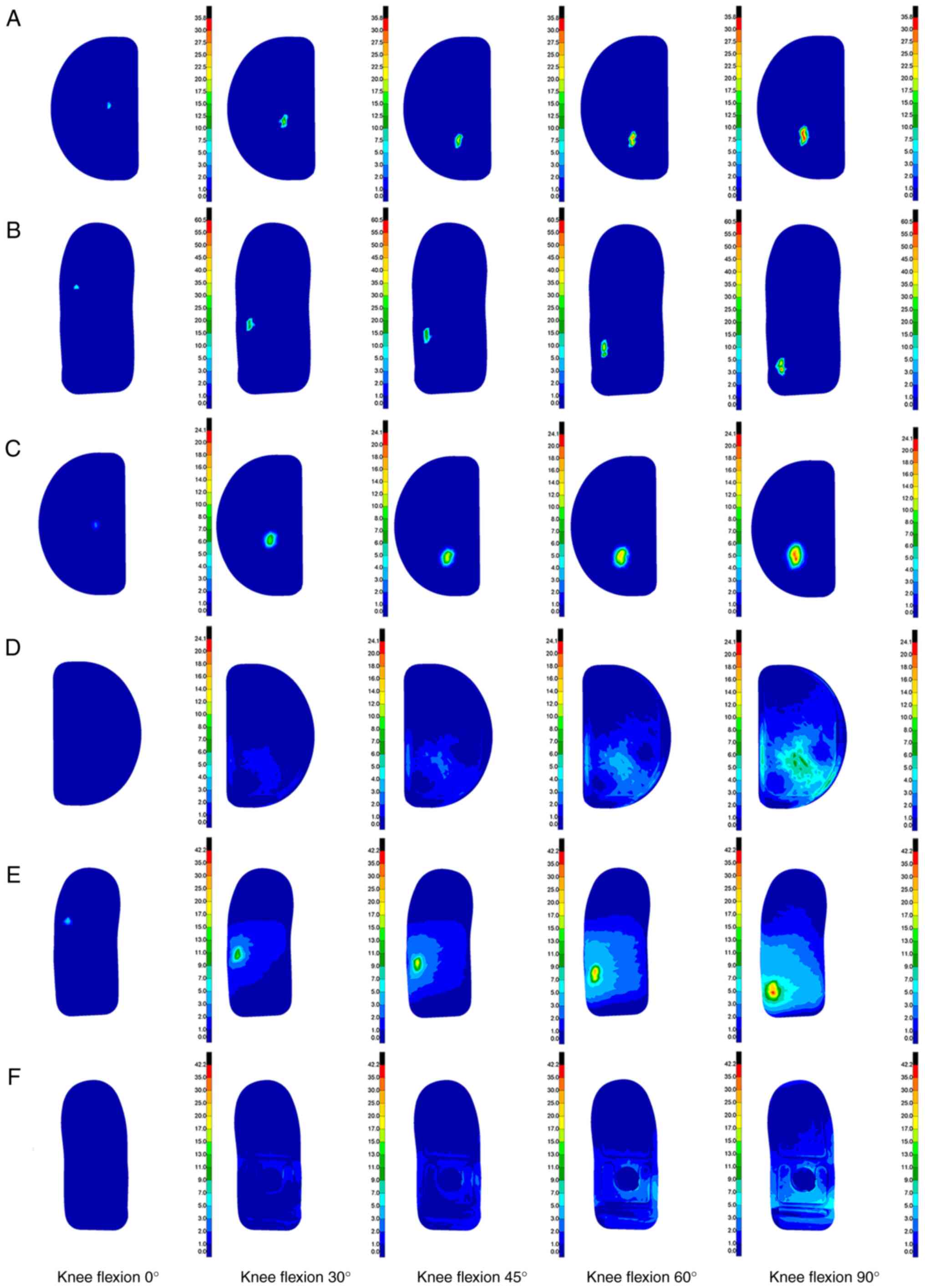
flexion from 0 to 90˚. Stress cloud diagrams were obtained at the
angles of 0, 30, 45, 60 and 90˚. Stress data were extracted every
5˚ to obtain an improved curve. The contact and Von Mises
equivalent stress cloud diagrams of the kinematic contact surface
of the femoral condylar prosthesis and tibial platform pad on the
operating side at different angles of knee flexion and prosthesis
retroversion were obtained. The contact stress reflects the index
parameter of the degree of friction damage to the structure, and
the equivalent stress reflects the index parameter of the degree of
yield fracture or damage to the structure.
Results
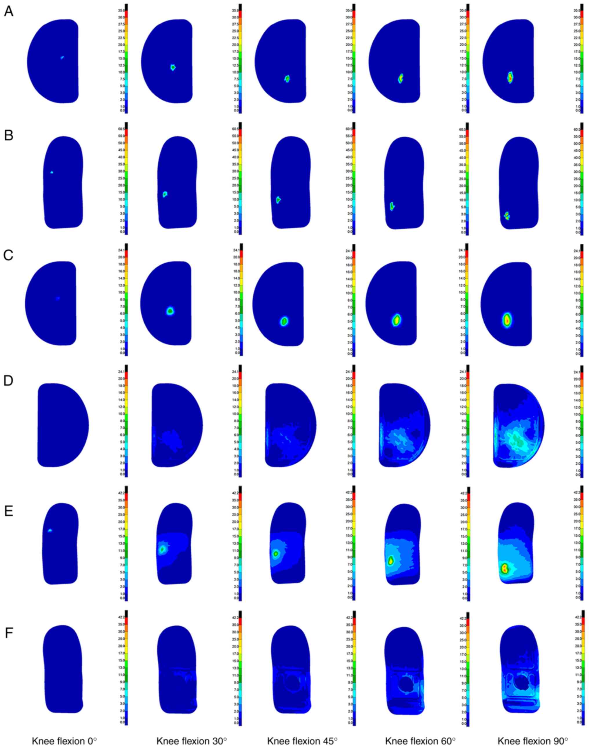
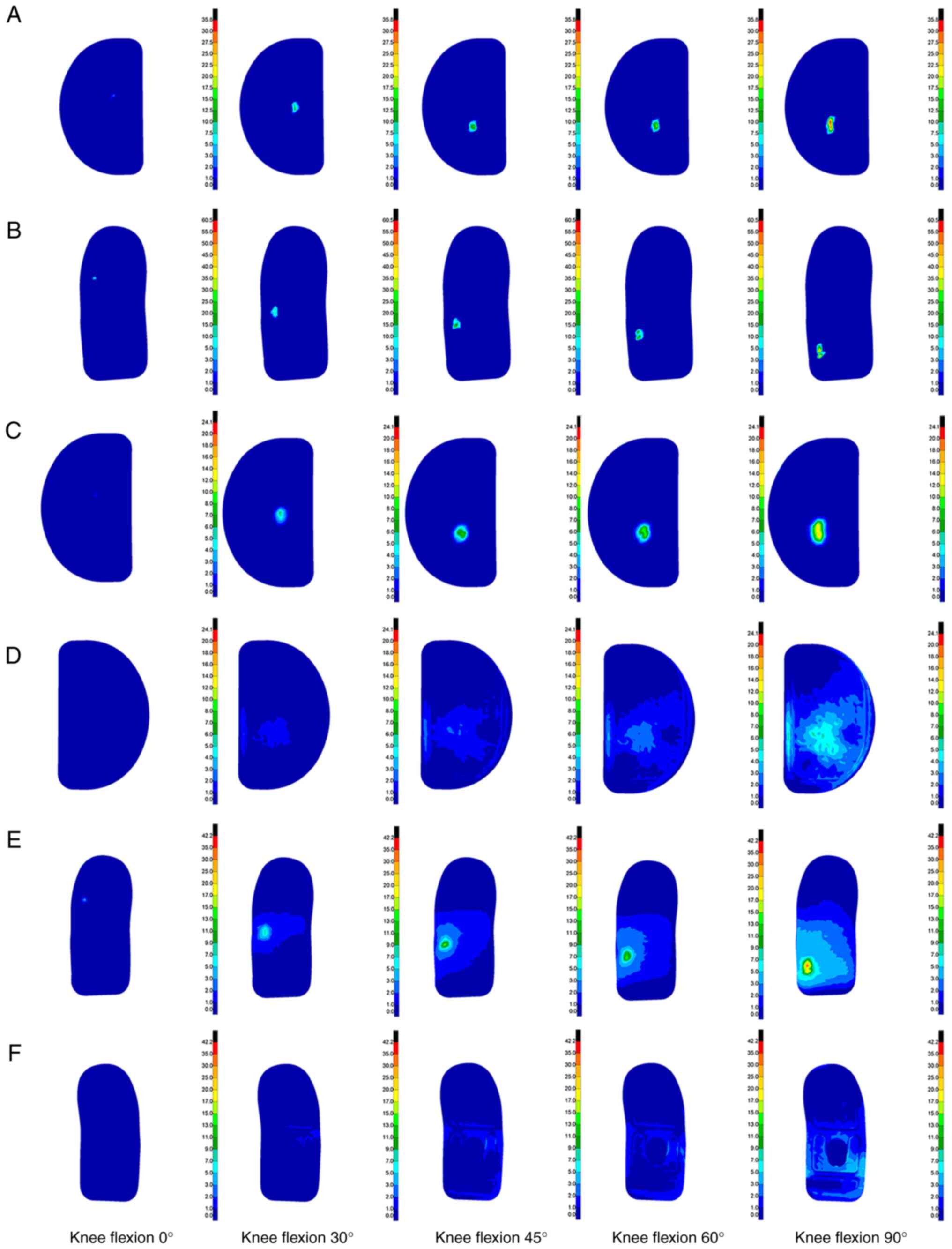
Stress distribution of implanted
prosthesis under different posterior inclination angles
The finite element method was used to simulate and
analyze three different tibial platform pad posterior inclination
angles (3, 6 and 9˚), and the biomechanical characteristics of the
knee joint structure at different knee flexion angles ranging from
0 to 90˚ were studied. Through analysis, a contact stress cloud
diagram and a Von Mises equivalent stress cloud diagram of the
kinematic contact surface of the femoral condyle prosthesis and
tibial platform pad were obtained at different knee flexion angles
and unicondylar fixed platform prosthesis retroversion angles. The
stress cloud diagrams of each group are demonstrated in Fig. 8, Fig.
9 and Fig. 10, and the
detailed peak data are shown in Table III, Table IV, Table V and Table VI.
| Table IIIPeak contact stress of tibial
platform pad contact under different posterior tilt angles
(MPa). |
Table III
Peak contact stress of tibial
platform pad contact under different posterior tilt angles
(MPa).
| Knee flexion angle
(˚) | 3˚ backward tilt
group | 6˚ backward tilt
group | 9˚ backward tilt
group |
|---|
| 0 | 6.58 | 4.06 | 2.45 |
| 5 | 7.08 | 6.14 | 4.11 |
| 10 | 7.62 | 7.05 | 6.19 |
| 15 | 7.09 | 10.25 | 5.01 |
| 20 | 12.37 | 9.14 | 8.58 |
| 25 | 17.61 | 8.69 | 8.96 |
| 30 | 19.91 | 11.66 | 11.84 |
| 35 | 21.36 | 19.11 | 11.27 |
| 40 | 19.59 | 19.18 | 13.82 |
| 45 | 23.12 | 19.37 | 16.63 |
| 50 | 24.69 | 23.16 | 20.74 |
| 55 | 27.41 | 23.05 | 18.41 |
| 60 | 28.95 | 25.71 | 19.11 |
| 65 | 30.05 | 31.53 | 23.14 |
| 70 | 32.25 | 30.61 | 26.64 |
| 75 | 35.05 | 32.95 | 31.98 |
| 80 | 34.00 | 34.02 | 31.21 |
| 85 | 32.97 | 34.36 | 34.17 |
| 90 | 35.68 | 35.31 | 34.65 |
| Table IVPeak contact stress of femoral
condyle prosthesis under different posterior tilt angles (MPa). |
Table IV
Peak contact stress of femoral
condyle prosthesis under different posterior tilt angles (MPa).
| Knee flexion angle
(˚) | 3˚ backward tilt
group | 6˚ backward tilt
group | 9˚ backward tilt
group |
|---|
| 0 | 10.24 | 9.34 | 5.38 |
| 5 | 12.75 | 11.44 | 7.16 |
| 10 | 13.54 | 15.12 | 9.39 |
| 15 | 8.89 | 13.29 | 10.87 |
| 20 | 19.56 | 12.99 | 10.22 |
| 25 | 22.98 | 10.25 | 12.56 |
| 30 | 20.47 | 20.46 | 11.71 |
| 35 | 23.65 | 23.12 | 16.26 |
| 40 | 21.93 | 22.6 | 16.46 |
| 45 | 25.51 | 22.35 | 26.79 |
| 50 | 40.46 | 25.54 | 25.08 |
| 55 | 38.63 | 39.92 | 22.6 |
| 60 | 38.52 | 39.39 | 31.98 |
| 65 | 54.69 | 44.76 | 29.78 |
| 70 | 57.97 | 48.42 | 33.47 |
| 75 | 55.53 | 50.98 | 35.25 |
| 80 | 54.83 | 47.58 | 44.83 |
| 85 | 59.24 | 56.84 | 49.52 |
| 90 | 60.43 | 58.02 | 54.94 |
| Table VPeak Von Mises equivalent stress of
tibial plateau pad under different posterior tilt angles (MPa). |
Table V
Peak Von Mises equivalent stress of
tibial plateau pad under different posterior tilt angles (MPa).
| Knee flexion angle
(˚) | 3˚ backward tilt
group | 6˚ backward tilt
group | 9˚ backward tilt
group |
|---|
| 0 | 2.45 | 2.19 | 1.19 |
| 5 | 3.27 | 3.9 | 2.66 |
| 10 | 3.55 | 4.25 | 2.87 |
| 15 | 3.85 | 5.86 | 3.14 |
| 20 | 6.17 | 4.48 | 3.88 |
| 25 | 7.62 | 5.32 | 4.11 |
| 30 | 10.12 | 7.44 | 6.39 |
| 35 | 11.22 | 8.94 | 5.48 |
| 40 | 11.13 | 10.45 | 7.45 |
| 45 | 13.03 | 9.91 | 8.02 |
| 50 | 13.04 | 10.33 | 8.56 |
| 55 | 14.18 | 12.16 | 8.34 |
| 60 | 15.84 | 14.81 | 9.35 |
| 65 | 15.13 | 18.41 | 10.95 |
| 70 | 18.15 | 19.36 | 12.19 |
| 75 | 19.04 | 17.21 | 13.79 |
| 80 | 19.93 | 20.41 | 19.13 |
| 85 | 24.09 | 18.58 | 20.43 |
| 90 | 21.71 | 20.34 | 15.47 |
| Table VIPeak Von Mises equivalent stress of
femoral condyle prosthesis under different posterior tilt angles
(MPa). |
Table VI
Peak Von Mises equivalent stress of
femoral condyle prosthesis under different posterior tilt angles
(MPa).
| Knee flexion angle
(˚) | 3˚ backward tilt
group | 6˚ backward tilt
group | 9˚ backward tilt
group |
|---|
| 0 | 5.34 | 7.12 | 3.46 |
| 5 | 6.52 | 5.98 | 5.36 |
| 10 | 9.55 | 11.38 | 4.97 |
| 15 | 5.85 | 9.58 | 6.91 |
| 20 | 13.44 | 8.48 | 8.24 |
| 25 | 11.76 | 7.17 | 8.83 |
| 30 | 15.14 | 10.22 | 7.69 |
| 35 | 17.17 | 15.54 | 10.63 |
| 40 | 17.96 | 13.41 | 8.75 |
| 45 | 21.29 | 15.44 | 15.56 |
| 50 | 24.76 | 19.88 | 16.77 |
| 55 | 24.82 | 21.59 | 16.18 |
| 60 | 27.66 | 25.55 | 18.93 |
| 65 | 33.00 | 30.01 | 19.12 |
| 70 | 37.99 | 30.64 | 28.88 |
| 75 | 36.91 | 31.95 | 26.72 |
| 80 | 41.58 | 29.79 | 27.6 |
| 85 | 38.22 | 37.74 | 29.97 |
| 90 | 42.17 | 36.67 | 34.25 |
Comparison of calculation results.
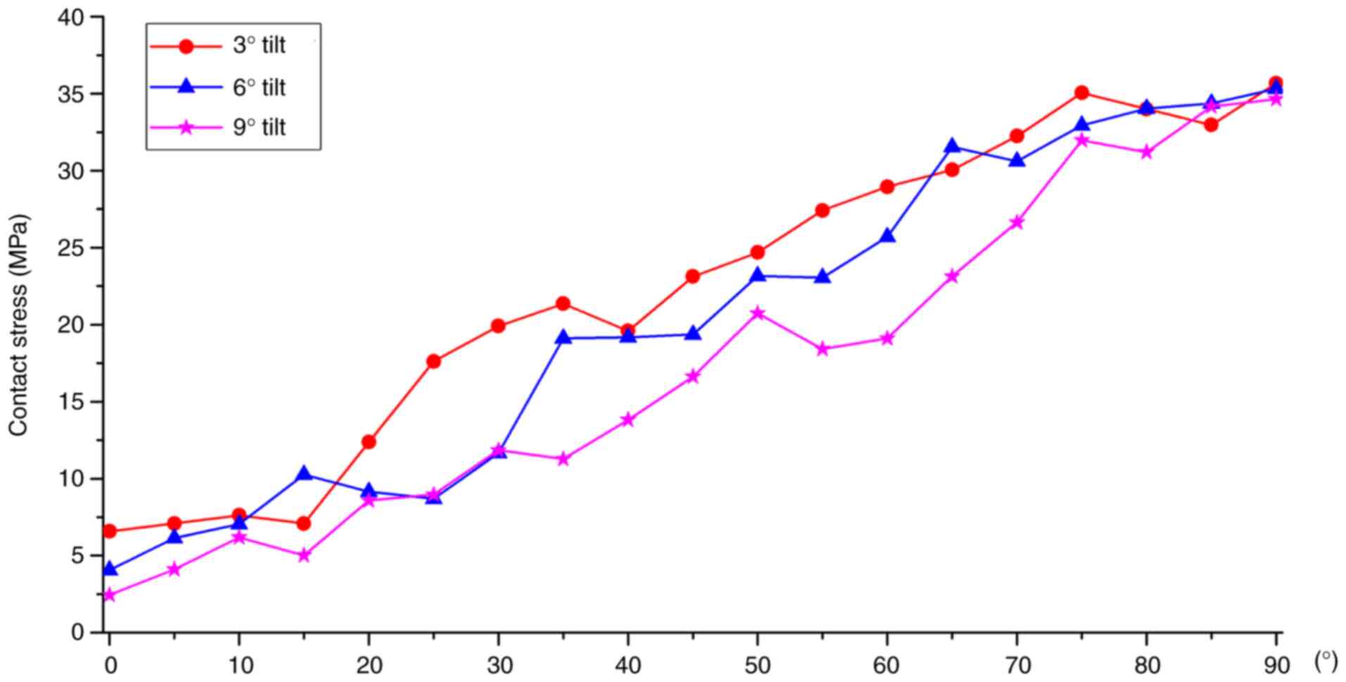
Contact stress comparison
A comparison of the tibial platform pad contact
stresses at different posterior tilt angles is shown in Fig. 11. Regarding the contact stress of
the tibial platform pad during knee flexion movement from 0 to 90˚,
the contact stresses corresponding to the three different tibial
platform pad posterior inclination angle groups were also
different. Among them, the peak contact stress of the tibial
plateau pad in the 3˚ posterior tilt group was ~6.58 to ~35.68 MPa.
The peak contact stress of the tibial plateau pad in the 6˚
posterior tilt group was ~4.06 to ~35.31 MPa. The peak contact
stress of the tibial plateau pad in the 9˚ posterior tilt group was
~2.45 to ~34.65 MPa. As the knee flexion angle gradually increased,
the contact stress on the tibial plateau pads in the three groups
gradually increased and the contact stress position gradually moved
toward the posterior side of the tibial plateau. During knee
flexion from 0 to 90˚, the overall trend of the tibial plateau pad
contact stress was as follows: 3˚ posterior inclination >6˚
posterior inclination >9˚ posterior inclination. The tibial
plateau pad contact stress corresponding to a 6˚ posterior tilt
between 0, 20, 40 and 90˚ knee flexion was closer to a 3˚ posterior
tilt. Compared with the tibial plateau pad with a 3˚ posterior
inclination, the average contact stress of the tibial plateau pad
with a 6˚ posterior inclination was reduced by ~10.41%, and the
average contact stress of the tibial plateau pad with a 9˚
posterior inclination was reduced by ~17.37%.
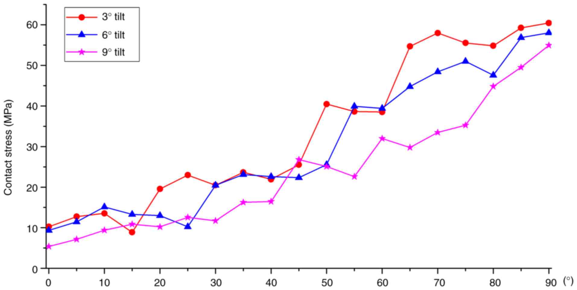
The comparison of the contact stresses of the
femoral condyle prosthesis at different posterior tilt angles is
illustrated in Fig. 12. During
knee flexion from 0 to 90˚, the contact stress of the femoral
condylar prosthesis in the three tibial platform pad posterior
inclination groups exhibited different characteristics.
Specifically, the peak contact stress of the femoral condyle
prosthesis in the 3˚ posterior tilt group ranged from 10.24 to
60.43 MPa. The peak contact stress range of the 6˚ backward tilt
group was 9.34 to ~58.02 MPa. The peak contact stress range of the
femoral condyle prosthesis in the 9˚ backward tilt group was 5.38
to ~54.94 MPa. As the knee flexion angle gradually increased, the
contact stress of the three groups of femoral condyle prostheses
exhibited a gradually increasing trend, and the position of the
contact stress gradually moved toward the posterior side of the
femoral condyle prosthesis. During knee flexion from 0 to 90˚, the
changing trend of the femoral condyle prosthesis contact stress was
3˚>6˚>9˚ posterior inclination. The contact stresses between
back tilts of 3˚ and back tilts of 6˚ were relatively close.
Compared with the contact stress of the femoral condyle prosthesis
with a posterior tilt of 3˚, the contact stress of the femoral
condyle prosthesis with a posterior tilt of 6˚ decreased by ~8.10%,
whereas the average decrease in the contact stress of the tibial
platform pad with a posterior tilt of 9˚ was ~20.93%.
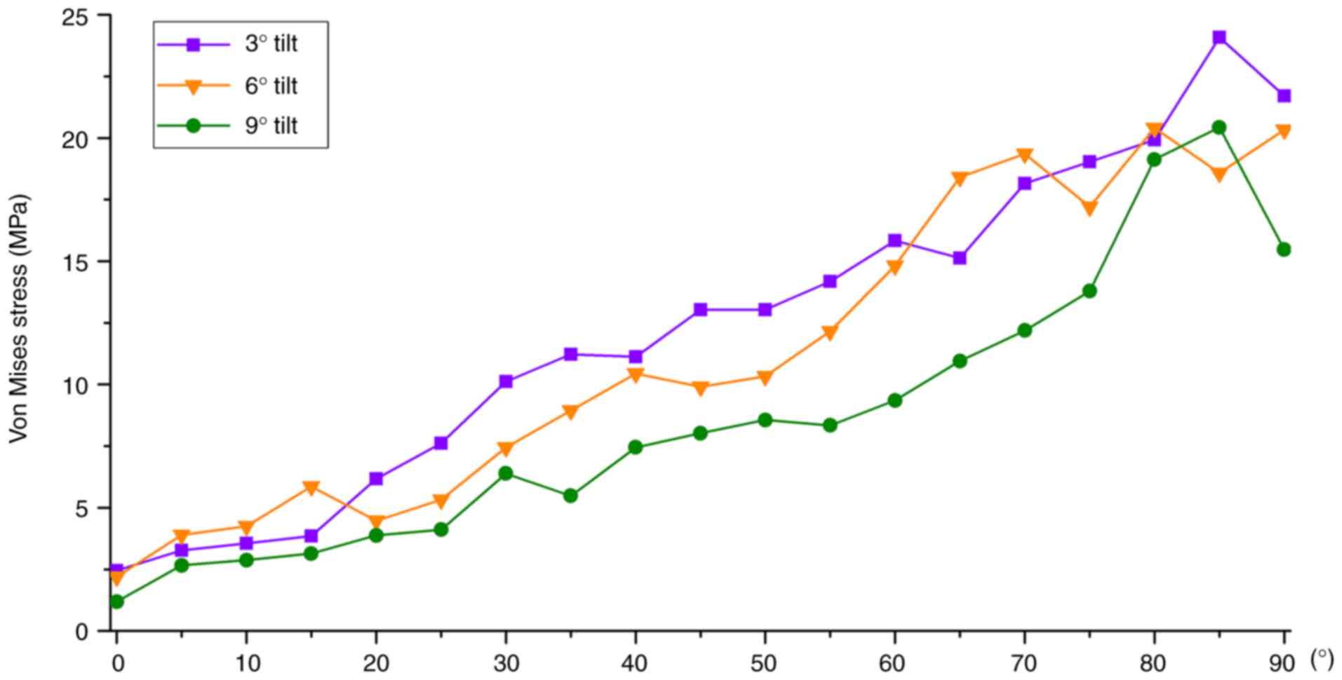
Von Mises equivalent stress
comparison
A comparison chart of the tibial platform pad Von
Mises equivalent stresses at different posterior tilt angles is
shown in Fig. 13. During knee
flexion from 0 to 90˚, there were differences in Von Mises
equivalent stress among the three tibial platform pad posterior
inclination angle groups. Among them, the Von Mises equivalent
stress peak value of the tibial platform pad in the 3˚ posterior
tilt group was 2.45 to ~21.71 MPa, the 6˚ posterior tilt group was
2.19 to ~20.34 MPa and the 9˚ posterior tilt group was 1.19 to
~15.47 MPa. As the knee flexion angle increased, the equivalent
stress in the three groups gradually increased and the position of
the equivalent stress gradually moved toward the posterior side of
the tibial plateau. During knee flexion from 0 to 90˚, the overall
trend in the Von Mises equivalent stress of the tibial platform pad
was as follows: 3˚>6˚>9˚ posterior inclination. Between 0 and
20˚, and between 60 and 90˚ of knee flexion, the tibial plateau pad
Von Mises equivalent stress corresponding to a posterior
inclination of 6˚ was closer to a posterior inclination of 3˚.
Compared with a posterior inclination of 3˚, the average decrease
in the Von Mises equivalent stress of the tibial platform pad with
6˚ of posterior inclination was ~5.44%, whereas the average
decrease in the Von Mises equivalent stress of the tibial platform
pad with 9˚ of posterior inclination was ~26.11%.
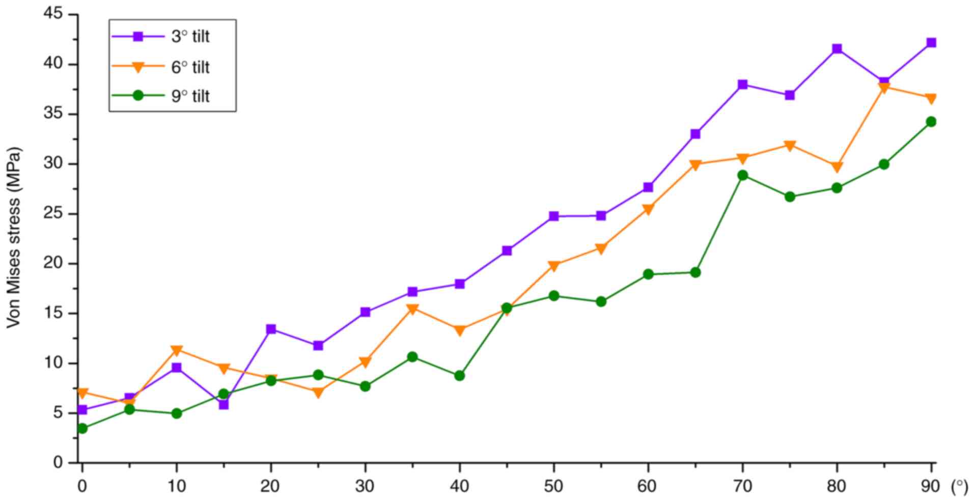
The comparison of the Von Mises equivalent stresses
of the femoral condyle prosthesis at different posterior tilt
angles is revealed in Fig. 14. In
the analysis of the Von Mises equivalent stress of the femoral
condylar prosthesis, for different tibial platform pad posterior
inclination angle groups, different structural equivalent stresses
were shown during knee flexion movement from 0 to 90˚. Among them,
the peak range of the Von Mises equivalent stress of the femoral
condylar prosthesis in the 3˚ posterior tilt group was 5.34 to
~42.17 MPa, the peak range of the 6˚ posterior tilt group was 7.12
to ~36.67 MPa, and the peak range in the 9˚ posterior tilt group
was 3.46 to ~34.25 MPa. As the knee flexion angle increased, the
Von Mises equivalent stress of the three groups of femoral condyle
prostheses gradually increased, and the position of the equivalent
stress gradually moved posteriorly. During knee flexion from 0 to
90˚, the overall changing trend of the Von Mises equivalent stress
of the femoral condylar prosthesis was as follows: posterior tilt
of 3˚>6˚>9˚. Compared with the femoral condylar prosthesis
with a posterior tilt of 3˚, the Von Mises equivalent stress of the
femoral condyle prosthesis with a posterior tilt of 6˚ decreased by
~9.87% on average, whereas the Von Mises equivalent stress of the
femoral condyle prosthesis with a posterior tilt of 9˚ decreased by
~19.76% on average.
Discussion
The determination of the posterior tilt angle of the
tibial prosthesis is an important link in UKA and affects the
long-term survival rate and clinical efficacy of the prosthesis
(27). Although the design of UKA
surgical instruments is becoming increasingly sophisticated, it
still relies heavily on the surgeon's experience to determine the
final osteotomy angle and prosthesis placement (28). Most UKA prostheses specify the
allowable range of tibial posterior tilt. However, tibial posterior
tilt is closely related to knee bone structural stress, ligament
tension, kinematics and platform wear rate; therefore, choosing the
optimal posterior tilt angle remains controversial (29). Therefore, relevant biomechanical
studies with high accuracy and predictability are important.
The present study used CT detection data to model
bone tissue and MRI to model soft tissue, retaining the main
structure without significantly simplifying the model. The bone and
soft tissue structures constructed by the model match the actual
anatomical structure and then underwent rigorous verification to
ensure the accuracy and effectiveness of the model. Based on the
normal model and using a fixed-platform prosthesis as a reference,
the first quasi-dynamic fixed-platform UKA model of the knee joint
under load-bearing conditions with different back inclination
angles was established. Based on the principles of motion
biomechanics and ideas of structural engineering mechanics, the
finite element method was used to study the biomechanical
characteristics of knee joint unicondylar fixation platform
prosthetic replacement surgery during knee flexion movement at
different angles of the tibial platform pad posterior tilt. The
distribution patterns and peak changes of the contact stress and
Von Mises equivalent stress of the femoral condylar prosthesis and
tibial platform pad during knee flexion at different angles were
observed. Weber et al (30)
studied the in vitro wear of four tibial prosthesis
posterior inclination angles (-4, 0, 4 and 8˚ ). It was found that
the amount of wear of the tibial prosthesis decreased at higher
posterior inclination angles (30). Through this finite element
calculation, it was found that during knee flexion movement from 0
to 90˚, the overall change trend of the contact stress and Von
Mises equivalent stress of the femoral condyle prosthesis and
tibial platform pad were as follows: Posterior tilt 3˚>6˚>9˚.
In the process of smaller (0-20˚) and larger knee flexion angles
(60-90˚), the stress values of 3˚ backward tilt and 6˚ backward
tilt were similar, and 3˚ backward tilt was slightly larger than
that of 6˚ backward tilt; the stress amplitude difference was
~within 10.41%. The stress value corresponding to 9˚ of backward
tilt was significantly smaller than that corresponding to 3˚ of
backward tilt and 6˚ of backward tilt (the stress reduction of 9˚
of backward tilt was ~17.37 to ~26.11% compared with that of 3˚ of
backward tilt). This can be explained by the gradual increase in
the posterior tilt angle of the tibial platform pad from 3 to 9˚
and the gradual decrease in the stress on the femoral condyle
prosthesis and tibial platform pad. As the posterior inclination
angle of the tibial platform pad increases, wear on the tibial
platform pad decreases. From a theoretical perspective, the use of
a platform pad is to be more durable and conducive to the long-term
survival of the prosthesis. However, judging from the current
biomechanical theoretical calculations, the entire knee joint
remains in stable motion during the current backward tilt of 3-9˚,
and no instability has occurred. Aleto et al (31) studied 13 cases of all-polyethylene
tibial prosthesis UKA that were revised because of medial tibial
plateau collapse. The average posterior inclination angle of the
posterior tibial plateau collapse was 12.8˚ and the average
posterior inclination angle of the anterior tibial plateau collapse
was 4.8˚, indicating that excessive posterior tilt can easily lead
to collapse of the posterior platform, serious bone loss and
significantly increase the difficulty of revision.
From a theoretical perspective, it is hypothesized
that simply pursuing a gradual increase in the posterior
inclination angle from 9˚ to reduce the stress on the tibial
plateau pad may not necessarily be feasible. For example, in
special sports conditions, such as running, jumping and
weight-bearing climbing, it is possible that the backward tilt of
the knee joint when the backward tilt angle is large will increase
the balance of the lower limbs after UKA, leading to the risk of
structural instability. As the retroversion angle increases to an
excessive level, the maximum stress on the femoral condylar
prosthesis and tibial platform pad moves more posteriorly. This may
lead to loosening of the tibial prosthesis, fractures, ligament
tears, accelerated pad wear, or structural instability.
The posterior tilt of the tibial prosthesis after
UKA also has a greater effect on the stress on the knee ligaments
and kinematic changes in the knee joint, thus becoming an important
factor affecting the long-term survival rate of the UKA prosthesis.
Suero et al (32) used
cadaver experiments to conduct a kinematic analysis of the UKA, a
fixed platform with a missing anterior cruciate ligament, and found
that when the tibial plateau posterior tilt was increased, the
anterior tibial translation was significantly increased. When the
posterior tilt is reduced, the anterior translation of the tibia
can be reduced to the same level as that in UKA when the anterior
cruciate ligament is normal. In an in vitro experimental
study on the mobile platform UKA, Weber et al (30) showed that increasing the tibial
posterior tilt can reduce the displacement between the pad and
tibial prosthesis, thereby reducing pad rear wear. They also
considered that increasing the tibial tilt could increase the
stability of the landing phase. The present study did not examine
the stress on the knee ligaments and kinematics of the knee joint
after UKA, which is a shortcoming of the present study that needs
to be improved in further research.
The present study has certain limitations: i)
Imaging data were obtained from CT and MRI scans of a single
volunteer, and the reconstructed knee joint model may only reflect
personal conditions, reducing its generalizability; ii) only 3
different tibial platform pad posterior inclination angles (3, 6
and 9˚) were selected for the analysis; and iii) the results
reflect only UKA with a fixed platform, and there are differences
between the biomechanical effects of UKA with fixed and mobile
platforms.
After this FEA, it was observed from a theoretical
perspective that when replacing a unicondylar fixed platform,
controlling the posterior inclination angle from 6 to 9˚ may be
more beneficial to the survival of the tibial platform pad than
from 3 to 6˚. Moreover, it is more conducive to reducing liner
wear. The results of FEA focus on the approximate solution process,
which is mainly qualitative and supplemented by quantitative
analysis, which can provide certain theoretical guidance and
suggestions for subsequent experiments or clinical operations. The
final surgical plan still needs to be verified in a large number of
animal or cadaver biomechanical experiments, as well as through
further clinical verification.
Acknowledgements
Not applicable.
Funding
Funding: The present study was supported by a grant from Heping
Hospital Affiliated to Changzhi Medical College (Institute Level
Research Fund; grant no. 2020-22).
Availability of data and materials
The data generated in the present study are included
in the figures and/or tables of this article.
Authors' contributions
PZ and YLW conceived and designed the study. LL and
HQY performed experiments. Data analysis and interpretation was
performed by PFH and XDL. PFH and XDL confirm the authenticity of
all the raw data. All authors read and approved the final
manuscript.
Ethical approval and consent to
participate
All procedures performed in studies involving human
participants were in accordance with the ethical standards of the
institutional and/or national research committee and with the
Declaration of Helsinki (1964) and its later amendments or
comparable ethical standards. The research protocol was reviewed
and approved by the Ethics Committee of Changzhi Second People's
Hospital (approval no. CZEYYL2023016; Changzhi, China). The
individual provided written informed consent before participating
in the study.
Patient consent for publication
Verbal informed consent was obtained from the
patient for publication of the present study and any accompanying
images.
Competing interests
The authors declare that they have no competing
interests.
References
|
1
|
Liu Y, Zhang Z, Li T, Xu H and Zhang H:
Senescence in osteoarthritis: From mechanism to potential
treatment. Arthritis Res Ther. 24(174)2022.PubMed/NCBI View Article : Google Scholar
|
|
2
|
Heekin RD and Fokin AA: Incidence of
bicompartmental osteoarthritis in patients undergoing total and
unicompartmental knee arthroplasty: Is the time ripe for a less
radical treatment? J Knee Surg. 27:77–81. 2014.PubMed/NCBI View Article : Google Scholar
|
|
3
|
van der List JP, Zuiderbaan HA and Pearle
AD: Why do medial unicompartmental knee arthroplasties fail today?
J Arthroplasty. 31:1016–1021. 2016.PubMed/NCBI View Article : Google Scholar
|
|
4
|
Saragaglia D, Bonnin M, Dejour D,
Deschamps G, Chol C, Chabert B and Refaie R: French Society of Hip
and Knee. Results of a French multicentre retrospective experience
with four hundred and eighteen failed unicondylar knee
arthroplasties. Int Orthop. 37:1273–1278. 2013.PubMed/NCBI View Article : Google Scholar
|
|
5
|
Ghosh P, Mohammad HR, Martin B, Campi S,
Murray DW and Mellon SJ: Low polyethylene creep and wear following
mobile-bearing unicompartmental knee replacement. Knee Surg Sports
Traumatol Arthrosc. 29:3433–3442. 2021.PubMed/NCBI View Article : Google Scholar
|
|
6
|
Grupp TM, Utzschneider S, Schröder C,
Schwiesau J, Fritz B, Maas A, Blömer W and Jansson V: Biotribology
of alternative bearing materials for unicompartmental knee
arthroplasty. Acta Biomater. 6:3601–3610. 2010.PubMed/NCBI View Article : Google Scholar
|
|
7
|
Müller PE, Pellengahr C, Witt M, Kircher
J, Refior HJ and Jansson V: Influence of minimally invasive surgery
on implant positioning and the functional outcome for medial
unicompartmental knee arthroplasty. J Arthroplasty. 19:296–301.
2004.PubMed/NCBI View Article : Google Scholar
|
|
8
|
Barbadoro P, Ensini A, Leardini A, d'Amato
M, Feliciangeli A, Timoncini A, Amadei F, Belvedere C and Giannini
S: Tibial component alignment and risk of loosening in
unicompartmental knee arthroplasty: A radiographic and
radiostereometric study. Knee Surg Sports Traumatol Arthrosc.
22:3157–3162. 2014.PubMed/NCBI View Article : Google Scholar
|
|
9
|
Pfeiffer FM: The use of finite element
analysis to enhance research and clinical practice in orthopedics.
J Knee Surg. 29:149–158. 2016.PubMed/NCBI View Article : Google Scholar
|
|
10
|
Weber P, Woiczinski M, Steinbrück A,
Schmidutz F, Niethammer T, Schröder C, Jansson V and Müller PE:
Increase in the tibial slope in unicondylar knee replacement:
Analysis of the effect on the kinematics and ligaments in a
weight-bearing finite element model. Biomed Res Int.
2018(8743604)2018.PubMed/NCBI View Article : Google Scholar
|
|
11
|
Iesaka K, Tsumura H, Sonoda H, Sawatari T,
Takasita M and Torisu T: The effects of tibial component
inclination on bone stress after unicompartmental knee
arthroplasty. J Biomech. 35:969–974. 2002.PubMed/NCBI View Article : Google Scholar
|
|
12
|
Sawatari T, Tsumura H, Iesaka K, Furushiro
Y and Torisu T: Three-dimensional finite element analysis of
unicompartmental knee arthroplasty-the influence of tibial
component inclination. J Orthop Res. 23:549–554. 2005.PubMed/NCBI View Article : Google Scholar
|
|
13
|
Luo CF: Reference axes for reconstruction
of the knee. Knee. 11:251–257. 2004.PubMed/NCBI View Article : Google Scholar
|
|
14
|
Ollivier M, Abdel MP, Parratte S and
Argenson JN: Lateral unicondylar knee arthroplasty (UKA):
Contemporary indications, surgical technique, and results. Int
Orthop. 38:449–455. 2014.PubMed/NCBI View Article : Google Scholar
|
|
15
|
Fukushima H, Hashimoto Y, Yoshiya S,
Kurosaka M, Matsuda M, Kawamura S and Iwatsubo T: Conduction
analysis of cement interface temperature in total knee
arthroplasty. Kobe J Med Sci. 48:63–72. 2002.PubMed/NCBI
|
|
16
|
Hai Y, Cheng S, Guo Y and Li S: Mesh
smoothing algorithm based on exterior angles split. PLoS One.
15(e0232854)2020.PubMed/NCBI View Article : Google Scholar
|
|
17
|
Mesfar W and Shirazi-Adl A: Biomechanics
of the knee joint in flexion under various quadriceps forces. Knee.
12:424–434. 2005.PubMed/NCBI View Article : Google Scholar
|
|
18
|
Wan C, Hao Z, Li Z and Lin J: Finite
element simulations of different hamstring tendon graft lengths and
related fixations in anterior cruciate ligament reconstruction. Med
Biol Eng Comput. 55:2097–2106. 2017.PubMed/NCBI View Article : Google Scholar
|
|
19
|
El'Sheikh HF, MacDonald BJ and Hashmi MSJ:
Finite element simulation of the hip joint during stumbling: A
comparison between static and dynamic loading. J Materials
Processing Technology. 143-144:249–255. 2003.
|
|
20
|
Mesfar W and Shirazi-Adl A: Biomechanics
of changes in ACL and PCL material properties or prestrains in
flexion under muscle force-implications in ligament reconstruction.
Comput Methods Biomech Biomed Engin. 9:201–209. 2006.PubMed/NCBI View Article : Google Scholar
|
|
21
|
Abramowitch SD, Zhang X, Curran M and
Kilger R: A comparison of the quasi-static mechanical and
non-linear viscoelastic properties of the human semitendinosus and
gracilis tendons. Clin Biomech (Bristol, Avon). 25:325–331.
2010.PubMed/NCBI View Article : Google Scholar
|
|
22
|
Lin W and Klein J: Recent progress in
cartilage lubrication. Adv Mater. 33(e2005513)2021.PubMed/NCBI View Article : Google Scholar
|
|
23
|
Mononen ME, Mikkola MT, Julkunen P, Ojala
R, Nieminen MT, Jurvelin JS and Korhonen RK: Effect of superficial
collagen patterns and fibrillation of femoral articular cartilage
on knee joint mechanics-a 3D finite element analysis. J Biomech.
45:579–587. 2012.PubMed/NCBI View Article : Google Scholar
|
|
24
|
Grood ES, Suntay WJ, Noyes FR and Butler
DL: Biomechanics of the knee-extension exercise. Effect of cutting
the anterior cruciate ligament. J Bone Joint Surg Am. 66:725–735.
1984.PubMed/NCBI
|
|
25
|
Bao HRC, Zhu D, Gong H and Gu GS: The
effect of complete radial lateral meniscus posterior root tear on
the knee contact mechanics: A finite element analysis. J Orthop
Sci. 18:256–263. 2013.PubMed/NCBI View Article : Google Scholar
|
|
26
|
Song Y, Debski RE, Musahl V, Thomas M and
Woo SLY: A three-dimensional finite element model of the human
anterior cruciate ligament: A computational analysis with
experimental validation. J Biomech. 37:383–390. 2004.PubMed/NCBI View Article : Google Scholar
|
|
27
|
Kim SJ, Bae JH and Lim HC: Factors
affecting the postoperative limb alignment and clinical outcome
after Oxford unicompartmental knee arthroplasty. J Arthroplasty.
27:1210–1215. 2012.PubMed/NCBI View Article : Google Scholar
|
|
28
|
Konyves A, Willis-Owen CA and Spriggins
AJ: The long-term benefit of computer-assisted surgical navigation
in unicompartmental knee arthroplasty. J Orthop Surg Res.
5(94)2010.PubMed/NCBI View Article : Google Scholar
|
|
29
|
Pourzal R, Cip J, Rad E, Laurent MP,
Berger RA, Jacobs JJ and Wimmer MA: Joint line elevation and tibial
slope are associated with increased polyethylene wear in
cruciate-retaining total knee replacement. J Orthop Res.
38:1596–1606. 2020.PubMed/NCBI View Article : Google Scholar
|
|
30
|
Weber P, Schröder C, Schmidutz F,
Kraxenberger M, Utzschneider S, Jansson V and Müller PE: Increase
of tibial slope reduces backside wear in medial mobile bearing
unicompartmental knee arthroplasty. Clin Biomech (Bristol, Avon).
28:904–909. 2013.PubMed/NCBI View Article : Google Scholar
|
|
31
|
Aleto TJ, Berend ME, Ritter MA, Faris PM
and Meneghini RM: Early failure of unicompartmental knee
arthroplasty leading to revision. J Arthroplasty. 23:159–163.
2008.PubMed/NCBI View Article : Google Scholar
|
|
32
|
Suero EM, Citak M, Cross MB, Bosscher MRF,
Ranawat AS and Pearle AD: Effects of tibial slope changes in the
stability of fixed bearing medial unicompartmental arthroplasty in
anterior cruciate ligament deficient knees. Knee. 19:365–369.
2012.PubMed/NCBI View Article : Google Scholar
|